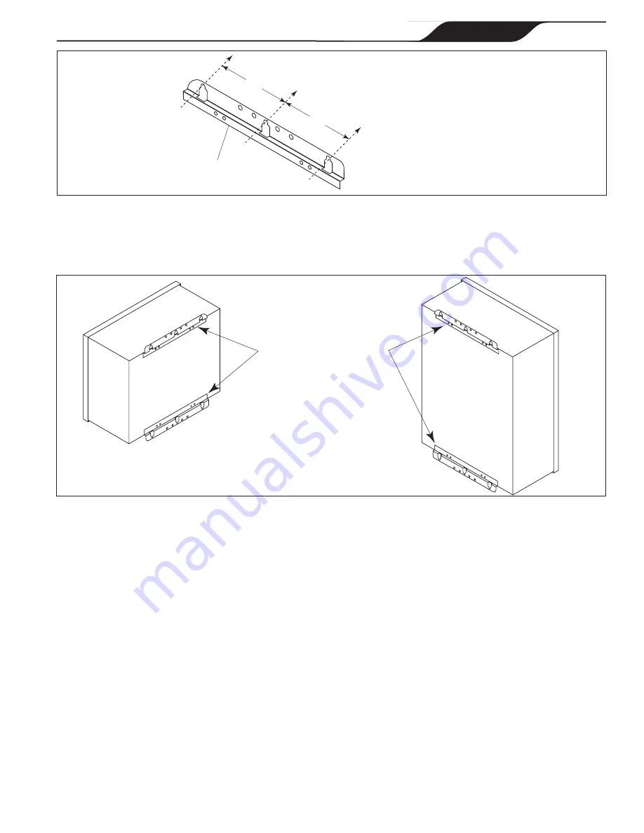
Figure 7. Mark Holes using Control/Power Center Mounting Bracket
Mounting Bracket
Mark Holes on Mounting Surface
4"
4"
4. Reinstall the mounting brackets to the top and bottom of the back of the control/power center using
the four (4) screws that were removed in
Step 2
. Ensure that the brackets are rotated from the original
shipping position (see Figure 8).
Figure 8.
Reinstall Mounting Brackets on Conrol/Power Center
5. Hang the control/power center on the surface using the three (3) holes drilled in
Step 3
. With the
control/power center in place, mark three (3) holes for the bottom bracket mounting.
NOTE
As with the top brackets, the bottom bracket requires three (3) mounting holes. The three (3) mounting holes
are four inches (4") apart center to center.
6. Drill the holes and install the screws.
7. Level the control/power center and tighten all screws, ensuring that the control/power center is securely
fastened to the mounting surface.
8. Check source voltage. (All units are factory wired for 240 VAC).
In order to use on 120 VAC, the
internal factory wiring of the power center must be changed. (See Figures 2b and 2c).
3.4 Earth Bonding (Grounding)
A solid, copper # 8 awg (8.4 mm
2
) wire is
recommended
for connecting the control/power center to a
permanent earth ground connection that is acceptable to the local inspection authority. Refer to your local
codes for the acceptable grounding wire gauge. Attach the bonding point located on bottom of the power
center to a common earth bonding point. Do not use the control/power center as the common bonding point.
Each piece of non-chlorinator related pool equipment requiring a ground should be bonded to the common,
approved, earth bonding point.
Reinstall Mounting Brackets
(Ensure to Rotate from
Original Shipping Position)
Page 15
ENGLISH
Page 15
ENGLISH
Jandy
®
AquaPure
®
/PureLink™ Power Center and Cell Kit
|
Installation and Operation Manual


