background image

9 MAINTENANCE

en-53

9.6

FUEL SYSTEM ____________________________________________________________

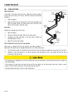
Water Separator

If the water is not removed from the fuel, damage to the fuel-injection 
system can occur. Every 100 hours, drain the water from the water 
separator.

 a

Stop the engine.

 b

Open the drain valve at the bottom of the water separator and 
drain the water. Water will drain before the fuel. When fuel 
drains from the valve, close the valve.

Fuel Filter

Replace the fuel filter every 400 hours.

 a

Stop the engine.

 b

Remove fuel filter cartridge. Clean any fuel that spills.

 c

Assemble new filter cartridge to the filter base. Tighten the 
cartridge with your hand.

 d

Bleed air from the fuel system.

How To Bleed The Air From The Fuel System

After water is drained from the fuel system, fuel filter cartridge is 
replaced or the fuel hoses are replaced, bleed the air from the fuel system.

 a

Turn the ignition switch to the RUN position, but do not start the engine. Operate the fuel pump for 20 seconds.

 b

Attempt to start the engine in 10 second intervals until the engine starts. The engine will remove any air 
remaining in the fuel hoses.


CAUTION

The Diesel fuel can damage your skin. Use gloves when you use Diesel fuel. If the fuel touches your skin, clean the 
area immediately.

The common rail fuel system will remove the air from the engine. Do not disconnect fuel hoses, tubes or open 
plugs on the common rail pump or the high-pressure fuel system.

Discard used Diesel fuel as shown in local regulations.

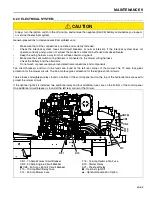
Water 
Separator

Drain 
Valve

Fuel 
Pump

From Tank

To Engine

To Tank

Fuel 
Filter

From 
Engine

!

Summary of Contents for HR-9016 Turbo

Page 1: ...must read the entire manual before attempting to set up operate adjust or service the machine GB HR9016 Turbo with ROPS 70542 HR9016 Turbo Kubota V3800 DICR T E4B Standard ROPS Option Factory Installe...

Page 2: ...ry 54 9 8 Charge the battery 55 9 9 Engine Exhaust 55 9 10 Diesel Particulate Filter 56 9 11 Hydraulic Hoses 57 9 12 Hydraulic Fluid 58 9 13 Hydraulic Filter 58 9 14 Tires 59 9 15 Wheel Mounting Proce...

Page 3: ...th the mower You must use the mower to cut the grass and not for any other purpose Compliance with the conditions or operation service and repair specified by the manufacturer are understood to be par...

Page 4: ...The engine serial number is also found on the engine block 2 3 SERIAL NUMBERS ________________________________________________________ Record the mower and engine numbers shown below Mower Number ___...

Page 5: ...use all of the necessary lifting equipment Use the correct tools and Personal Protective Equipment PPE and take instruction from the technical manuals applicable to the mower Remove and keep correctly...

Page 6: ...any switch c Never operate equipment that is not in correct order or without decals guards shields deflectors or other protective devices fastened DO NOT operate the cutting unit without the discharg...

Page 7: ...ble g When you drive in the reverse direction look behind you and down to make sure the path is clear Do not operate the cutting units when you drive in the reverse direction h Use caution when you go...

Page 8: ...ainers inside a vehicle or on a truck or trailer with a plastic liner Always put the fuel container on the ground away from your vehicle before you fill the container e Refuel the mower before you sta...

Page 9: ...can have enough force to enter your skin If hydraulic fluid has entered your skin a doctor must remove the hydraulic fluid surgically within a few hours or gangrene can occur o When you service the h...

Page 10: ...tact your Authorized Jacobsen Dealer Your Dealer knows the current methods to service this equipment WARNING The Interlock System on this mower prevents the operation of the mower unless a The parking...

Page 11: ...tem Turbo Charged Gross Intermittent Power 99 9 hp 74 5 kW 2600 rpm Torque 247 1 ft Lb 335 Nm 1500 rpm Maximum Speed 2800 50 rpm No Load Low Idle 1100 25 rpm No Load Rotation Counter clockwise viewed...

Page 12: ...171 inch 434 3t cm J Wheel Base 83 inch 210 8 cm K Front Wheel Track 54 5 inch 138 4 cm L Rear Wheel Track 53 inch 134 6 cm M Height Top of Canopy 96 inch 243 8 cm N Front Deck Width of Cut 92 inch 22...

Page 13: ...SPECIFICATIONS 4 en 12 K L D B A P P N C J H M E G...

Page 14: ...el motors and 12 5 in3 205 5 cc rear wheel motors Cutting Unit Drive 1 01 in3 16 55 cc hydraulic motors connected to the cutting unit Mow Speed 0 8 5 mph 0 13 68 kph Transport Speed 0 20 mph 0 32 2 kp...

Page 15: ...06 42 EC By compliance to Whole Body EN1032 2003 Information Supplied for Physical Agents Directive 2002 44 EC By reference to Whole Body Standards BS EN ISO 2631 1 1997 4 6 NOISE ____________________...

Page 16: ...fluid is ISO VG68 Grease Texaco Starplex 2EP Moly NLGI Grade 2 EP Lithium Complex Grease containing Molybdenum Disulfide or equivalent HR9016T Blade Length 21 in 53 3 cm Number of blades Front Deck 5...

Page 17: ..._________________________________ Kit Number 1004049 4 10 3 REPLACEMENT BLADES __________________________________________________ Standard Blade 2810030 High Lift Blade 3007759 CE Blade 4119024 4 10 4...

Page 18: ...4 10 9 THIRD PARTY ACCESSORIES ______________________________________________ Snow Thrower Rotary Broom Loftness Specialty Equipment Inc M B Companies Inc South Highway 4 1200 Park Street Box 148 Hec...

Page 19: ...Aflv l Motor Kubota V2403 CR E4B Diesel Net Installed Power ist instalovan v kon Installeret nettoeffekt Netto ge nstalleerd vermogen Installeeritud netov imsus Asennettu nettoteho Puissance nominale...

Page 20: ...o operador Nivelul zgomotului la urechea operatorului Hladina hluku p sobiaca na sluch oper tora Raven hrupa pri u esu upravljavca Nivel sonoro en el o do del operador Ljudniv vid f rarens ra H va ast...

Page 21: ...atura da pessoa com poderes para emitir a declara o em nome do fabricante que possui a documenta o t cnica que est autorizada a compilar o processo t cnico e que est estabelecida na Comunidade Semn tu...

Page 22: ...operation keep persons and animals away DANGER To prevent injury while you do work on the battery 1 Connect the negative BLACK wire after the positive RED wire Remove the negative BLACK wire before t...

Page 23: ...ARNING The front deck is heavy and can cause injury or damage if allowed to fall Always use correct methods when you lift or lower the deck to the service position WARNING To prevent injury or be thro...

Page 24: ...r screen hydraulic oil cooler and radiator of dirt or cut grass When you stop for fuel check the engine oil level To lift the front deck to the service position 1 Rotate the anti sway mechanism down 2...

Page 25: ..._________________ Traction pedal operation Steering Assist Pedal Decal Patent Decal Guaranteed Sound Power Level 3008521 BRAKE 360053 Manufactured under one or more of the following U S patents 530969...

Page 26: ...r s 1 8 th k when setting cut height 3009317 1 2 3 4 5 6 7 8 A B C D E F R Cut Height Bracket Hole Arm Hole Wheel Mounting Wheel Mounting F A 3 1 F B 1 1 1 2 F C 2 2 F D 3 2 1 2 F E 4 3 F B 5 3 1 2 F...

Page 27: ...he parking brake stop the engine and remove the key 4 Keep your hands feet and clothing away from parts that move 5 Never carry passengers Keep persons away CAUTION When you do not operate the engine...

Page 28: ...5 DECALS en 27...

Page 29: ...CONTROLS 6 en 28 6Controls 6 1 OPERATOR COMPARTMENT________________________________________________ 6 2 6 3 6 4 6 7 6 6 6 5...

Page 30: ...en 29 6 2 CONTROL PANEL _________________________________________________________ P E F 6 2 1 6 2 2 6 2 3 6 2 4 6 2 5 6 2 6 6 2 7 6 2 8 6 2 9 6 2 10 6 2 11 6 2 12 6 2 13 6 2 14 6 2 15 6 2 16 6 2 17 6...

Page 31: ...reverse position the mower speed will decrease Do Not engage the 4WD reverse switch with the traction pedal in the forward direction When the switch is released the mower will return to 2WD in the rev...

Page 32: ...position See 9 10 Put the switch in the center position to allow automatic Active Regen Operation of the mower is not changed during Active Regen See 9 10 When the Regen Request light flashes press an...

Page 33: ...Filter DPF light module has a Regen Request light and High Exhaust Temperature light that indicate the status of the DPF Regen system When a Parked Regen cycle is necessary the front amber light will...

Page 34: ...area The red hydraulic filter light indicates that the hydraulic filter must be replaced Return the mower to the service area and replace the filter The red hydraulic level light indicates a low flui...

Page 35: ...AUGE ____________________________________________ The water temperature gauge shows the temperature of the engine coolant The normal engine operation temperature is between 160 to 230 F 71 110 C If th...

Page 36: ...hold the lever until the left wing deck has lifted When the left wing deck is lifted the left wing deck blades will stop 6 2 16 RIGHT WING DECK LEVER_________________________________________________ T...

Page 37: ...needed for the cutting units to lower will increase 6 2 18 PANEL LATCH ___________________________________________________________ The panel latch holds the control panel closed while the mower is in...

Page 38: ...it the forward speed To travel at transport speed rotate mow stop to the transport position 6 4 STEERING ASSIST PEDALS ________________________________________________ Press the left or right steering...

Page 39: ...r the operator The seat height control adjusts the height of the seat To lift the seat lift the seat height lever To lower the seat push the seat height lever down Release the lever to set the adjustm...

Page 40: ...l supply radiator coolant level crankcase oil level and air cleaner indicator When the engine is cold all fluids must be at the full level mark Check the radiator and oil cooler fins for dirt or grass...

Page 41: ...al is in the NEUTRAL position and the PTO switch is in the OFF down position The engine will start TEST 2 The engine must not start if the PTO switch is in the ON position TEST 3 The engine must not s...

Page 42: ...the equipment can cause injuries to persons and cause damage to the equipment 9 When you are not mowing grass always turn off the PTO switch 10 Before you move across or operate on the paths or roads...

Page 43: ...E _____________________________________________________ To stop and park the mower in normal conditions 1 Turn the PTO switch to the OFF position Drive the mower to a flat and level area to park the m...

Page 44: ...hen you drive the mower on rough ground public roads or the mower is on a trailer To engage transport locks 1 Completely lift the wing decks 2 Engage the parking brake stop the engine and remove the k...

Page 45: ...the cutting units are lowered the blades will start turning 3 To lift the front and rear cutting units pull and hold the lift levers until the cutting units are fully lifted The blades will stop turni...

Page 46: ...rive toward the bottom of a slope with a high angle lower the cutting units to the ground This procedure makes sure the mower does not turn upside down 6 Correct tire pressure is necessary for maximum...

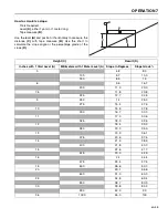
Page 47: ...s with 1 Yard Level A Millimeters with 1 Meter Level A Slope in Degrees Slope Grade 3 4 8 8 3 100 5 7 10 0 150 8 5 15 6 9 5 16 7 200 11 3 20 0 7 5 11 8 20 8 225 12 7 22 5 9 250 14 25 0 275 15 4 27 5 1...

Page 48: ...move the plastic cover behind the seat and open the bypass valve before you tow the mower The bypass valve lets the mower be moved without the engine started and prevent possible damage to the hydraul...

Page 49: ...9 5 Each Two weeks 100 Hours Lubricate grease fittings F2 Check air filter Check fan belt tension Drain water from fuel system See 8 2 See 9 4 See 10 3 See 9 6 Each month 250 Hours Replace engine oil...

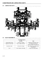
Page 50: ...Engine Oil with Filter 12 Quart 11 35 liter 10W 30 API Classification CJ 4 Hydraulic Oil with Filter 50 U S Gallon 189 liter ISO VG68 Hydraulic Fluid 5001404 5 Gallon 18 9 liter Pail Radiator Coolant...

Page 51: ...he engine When you follow the engine manufacturer instructions you will make sure of the maximum service life of the engine The replacement engine manuals are available from the engine manufacturer Th...

Page 52: ...and clean with a cloth c Drain the engine oil into a container d Replace the drain plug and fill the engine with the correct quantity and grade of oil through the filler Change Engine Oil Filter a Rem...

Page 53: ...an approved container The spout on the container must fit inside the fuel filler neck Never use the containers that are not approved to keep or transfer fuel Fill the fuel tank to less than 1 inch 2...

Page 54: ...How To Bleed The Air From The Fuel System After water is drained from the fuel system fuel filter cartridge is replaced or the fuel hoses are replaced bleed the air from the fuel system a Turn the ign...

Page 55: ...o jump start the mower check the condition of the drained battery b Connect the positive battery terminal of the charged battery to positive battery terminal of the drained battery c Connect the negat...

Page 56: ...ion and the Engine Manual for information about the DPF system If you sense a change in the color or sound of the exhaust stop the engine immediately Identify the problem and have the system repaired...

Page 57: ...nless Inhibit Regen switch is in the INHIBIT position Normal Active Regen is completed in approximately 20 minutes If the particle material level does not decrease to the Passive Regen level in 30 min...

Page 58: ...hydraulic component tag or mark the location of each hose then clean the area around the fittings To prevent dirt to enter the hydraulic system when you disconnect the component be prepared to assembl...

Page 59: ...m is protected by two 10 micron filters The charge filter is found on the left side frame rail below the radiator The return filter is found on the left side of the hydraulic oil cooler Flow through t...

Page 60: ..._________________________________ A Roll Over Protective Structure ROPS is included with this mower Inspect the ROPS periodically for loose hardware or damage Every 400 hours inspect the seat seat bel...

Page 61: ...and oil cooler To move the oil cooler to the service position 1 Remove the knobs and the shield 2 Release the end cap latches Remove the screws from the left side and the right side caps 3 Move the sc...

Page 62: ...the maximum of one half inch 1 3 cm blade loss has occurred do not sharpen more replace the blade To prevent a blade that is not balanced make sure an equal amount of material is removed from both end...

Page 63: ...t rear corner of the mower The 70 amp fuse gives protection for the mower circuits The 90 amp fuse gives protection for the engine control circuits Twelve fuses and eighteen relays found on bottom of...

Page 64: ...ight Fuse K1 Ignition Switch I Relay K2 Ignition Switch A Relay K3 Ignition Switch S Relay K4 Brake Start Relay K5 Brake Run Relay K6 Neutral Start Relay K7 Neutral Run Relay K8 Neutral Cruise Relay K...

Page 65: ...ners To keep the original high polish of the fiberglass parts wax with a good grade of one step cleaner wax Repair damaged metal surfaces and use Jacobsen touch up paint Apply wax to the equipment for...

Page 66: ...il filter Install the drain plug and fill the engine with oil Torque the drain plugs to 22 ft Lb 30 Nm Clean the outside surface of the engine Paint bare metal or apply a thin layer of rust preventati...

Page 67: ...nts fuel anti freeze follow your local state or federal recommended procedures 10 2 MOW SPEED______________________________________________________________ The cutting quality is improved at speeds lo...

Page 68: ...he Engine manual If the belt tension is not correct loosen the alternator mounting bolts and adjust the alternator until the correct belt tension is set Tighten the alternator mounting bolts Compresso...

Page 69: ...to the wiring harness i Lower the mower to the ground j Connect the pedal linkage to the pump and assemble the switch bracket Check the neutral switch and forward switch adjustment k Start the engine...

Page 70: ...h adjustment is done at the traction pump Adjust the switch so that the switch contacts are open with the traction pedal is in the NEUTRAL position The switch contacts must close through the full forw...

Page 71: ...st the parking brake 2 When the parking brake disengaged rotate the adjustment knob to the right side 90 degrees Engage and disengage the parking brake Repeat this step until a snap over center action...

Page 72: ...the engine 3 Note the location of the gauge wheel height of cut pins Remove the gauge wheel height of cut pins 4 Start the engine and completely lift the front deck Stop the engine 5 Manually lift the...

Page 73: ...of 1 2 inch 1 3 cm spacers and one 1 16 inch 0 16 cm thrust washer onto the caster yoke The trust washer must be on top of the spacers on the caster yoke d Slide the caster wheel yoke into the pivot...

Page 74: ...8 9 cm 2 1 Center Position Holes 4 inch 10 2 cm 3 0 Center Position Holes 4 inch 10 2 cm 0 3 Upper Position Holes 4 1 2 inch 11 4 cm 1 2 Upper Position Holes 5 inch 12 7 cm 2 1 Upper Position Holes 5...

Page 75: ...cm Center Position Holes 2 1 2 to 4 inch 6 3 to 10 2 cm Lower Position Holes 1 to 2 1 2 inch 2 5 to 6 3 mm Caster Yoke 1 2 inch 1 3 cm Spacer 1 16 inch 0 16cm Spacer 1 2 inch 1 3 cm Spacer 1 8 inch 0...

Page 76: ...etween the ground and the blade Move an 1 8 inch 0 32 cm spacer from below the pivot block to above the pivot block to decrease the distance between the ground and the blade 4 Measure the distance fro...

Page 77: ...ADJUSTMENTS 10 en 76 A A B B C C C C Shim Shim Plastic Plate Support Arm Stop Bracket Pivot Block 1 8 inch 0 32cm Spacer 1 8 inch 0 32cm Spacer 1 16 inch 0 16cm Spacer Support Bracket...

Page 78: ...the cutting units 4 Front Deck The front deck limit switch is found on the frame by the right lift arm Adjust the limit switch so the sensing area of the switch is centered over the bottom edge of the...

Page 79: ...09 1 4 20 in lb Nm 75 8 4 100 11 3 107 12 1 143 16 1 9 16 18 ft lb Nm 92 124 122 165 129 174 172 233 1 4 28 in lb Nm 85 9 6 115 13 0 120 13 5 163 18 4 5 8 11 ft lb Nm 113 153 151 204 159 215 211 286 5...

Page 80: ...poorly 1 Fuel level low fuel or fuel filter dirty 1 Fill with fresh fuel Change fuel filter Bleed fuel lines 2 Air cleaner dirty 2 Inspect and replace air filter 3 Injectors fuel pump 3 Consult engine...

Page 81: ...tral Run When the operator leaves seat with traction pedal not in the NEUTRAL position the relay disconnects power to the alternator IG circuit NT3 K8 Neutral Cruise When the traction pedal is in the...

Page 82: ...disables the mower run cir cuit K16 Auxiliary The relay supplies power to the auxiliary circuit with the ignition switch in RUN position The relay disables the auxiliary circuit with the ignition swi...

Page 83: ...arding is a repeated pattern of different cutting heights that causes an appearance that is like a wave In most cases the wave tip to tip distance is approximately 6 8 in 15 20 cm A change in the colo...

Page 84: ...medy HOC height of cut settings are different from one side of a cutting unit to the other side or from one cutting unit to another unit Check HOC adjustment of cutting units See 10 13 Worn deck caste...

Page 85: ...light green or brown A low HOC setting or turf that is not level can cause scalping Probable Cause Remedy HOC height of cut settings are lower than normal Check and adjust the HOC settings See 10 13...

Page 86: ...edy Edge of the cutting blade s are not sharp Sharpen the blade s See 9 19 Cut ground speed is higher than normal Reduce the cut ground speed The grass is higher than the level at which the mower can...

Page 87: ...faster than the mower can turn and cut correctly The cutting units do not overlap around turns or on side hills Turn at a speed that will allow the cutting units to overlap Change the direction of cu...

Page 88: ...ed at one end of cutting unit s or between cutting units Windrowing can make a line in the direction of travel Probable Cause Remedy The grass is higher than the level at which the mower can cut corre...

Page 89: ...adjustment from one cutting unit to another unit Probable Cause Remedy HOC is different from one cutting unit to another unit Check and adjust the HOC on cutting units to same height See 10 13 Differ...

Page 90: ...13 NOTES en 89 13Notes...

Page 91: ...NOTES 13 en 90...

Page 92: ...n Performance Matters Equipment from Jacobsen is built to exacting standards ensured by ISO 9001 and ISO 14001 registration at all of our manufacturing locations A worldwide dealer network and factory...

Reviews: