Remote Control System TT801 – User Guide
MU-TT801-AN rev.6 September 2009
12
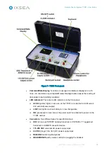
Figure 7 - TT801 Front panel
•
Command/Data Display
: Functions, messages
and data are displayed on a 16
lines
×
20 characters Liquid Crystal Module. Backlight option makes the reading of
data easier in bad visibility conditions.
•
LED indicators
: There are 3 LED indicators on the front panel:
AC/DC
(yellow) lights on as soon as the TT801 is connected to AC Mains or
24V external power supply
LOW
(red) lights on when battery is in low charge state
ON
(green) light on as soon as the power switch is activated to power on the
TT801 cabinet
•
Connectors
: Five different types for specific functions:
XDC
to hook up PET801P dunking transducer or PET661S-TT ruggedized
transducer or AM661S acoustic module
115-230 VAC
universal AC power supply input
24 VDC
(range 18 to 36 V) DC power supply input
RS232/422
serial input/output link
HEADPHONES
(with volume control) for plugging the headset
Summary of Contents for TT801
Page 1: ...TT801 Remote Control System User Guide...
Page 2: ......


