Engine Control System 1A-7
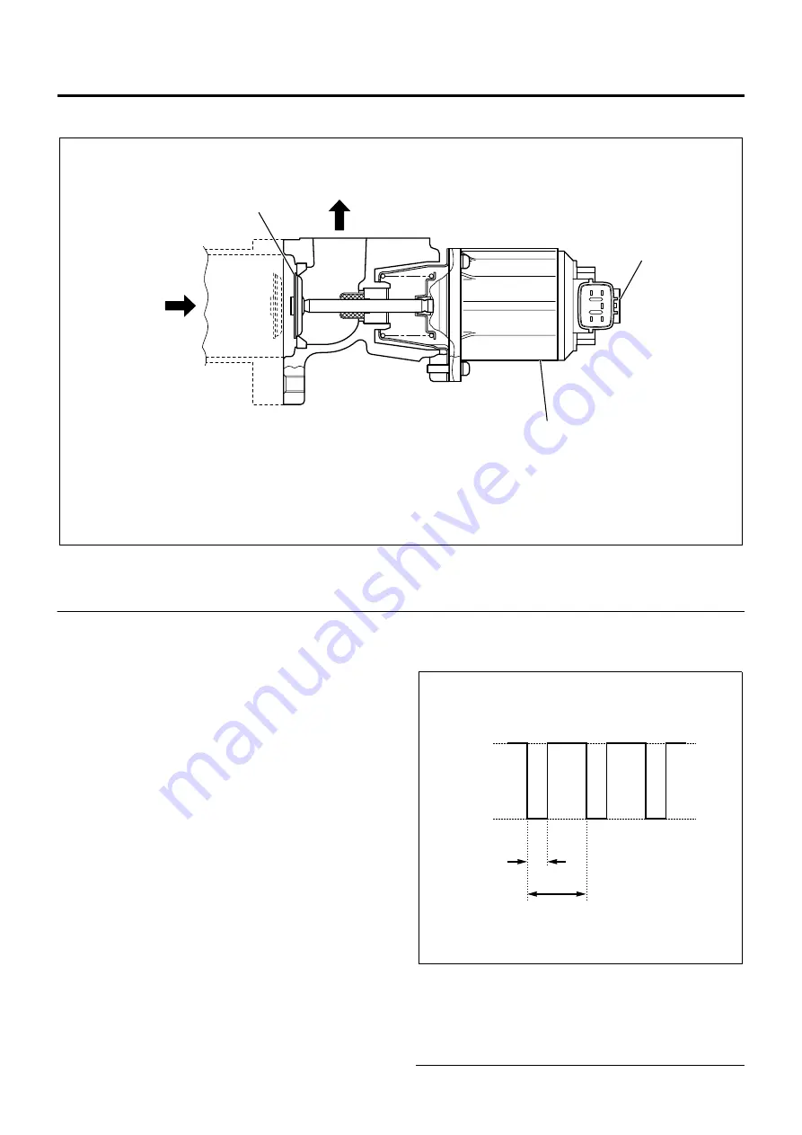
EGR Control
Legend
1. EGR valve
2. EGR valve position sensor
3. EGR DC motor
The EGR control system recirculates a portion of
exhaust gas to the intake to drop the combustion
temperature and thus reduce NOx. This control is
made by opening and closing the EGR valve. The EGR
valve is operated by the DC motor and changing the
duty (see Note 1) opens and closes the valve. This
EGR valve is fully closed in the normal state (i.e., the
DC motor is inactive) and gradually enlarges the
opening as the duty is increased. The ECM uses the
EGR valve position sensor to comprehend the working
condition of the EGR valve. When the valve opening
gets larger (the duty is increased), the output voltage of
the EGR valve position sensor becomes higher.
The EGR control is initiated when parameters such as
engine speed, engine coolant temperature, accelerator
position, atmospheric pressure, and system voltage
meet the required conditions, and the EGR valve
opening is calculated from engine coolant temperature,
engine speed, and desired injection quantity. The ECM
determines the drive duty of the DC motor based on
this valve position and drives the motor. The EGR
control is turned off when the exhaust brake is
operated, the PTO is working, the AP sensor fails, the
ECT sensor fails, the EGR system fails, or the intake
throttle system fails.
There is an opposing relationship between EGR control
and intake throttle control. When the intake throttle
valve is opened, the EGR valve is closed, and vice
versa.
Note 1: Duty (%) = T (*) / 5 (msec) × 100
* T = Duty input time (see motor drive voltage
waveform)
Legend
1. 24V
2. 0V
3. T (duty input time)
4. 5 msec
LNW21AMF005801
3
2
1
1
2
3
4
LNW21ASH009101
Summary of Contents for 4HL1
Page 267: ...No LG4HL WE 0229DOM...


