15
inVENTer
®
iV12-Smart
®
/iV12-Smart
®
Corner ventilation system
•
Installation and operating instructions
PreParaTions Prior To insTallaTion
3.2
Dimensioned drawings
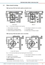
Wall opening iV12-smart with weather protection hood
Ø
180
y ≥ 250
145
140
180
2
1
5
3
6
4
Ø
180
136
177
y ≥ 250
180
2
1
3
4
5
6
≥ 250
1)
≥ 250
1)
≥ 450
2)
WSH-Smart
WSH-09
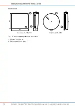
Fig. 11: Dimensioned drawing for wall opening
1 Wall opening for new builds
4 Outer edge of embrasure (ins. w. plaster)
2
Wall opening for existing buildings
5 Door/window frame
3 Position of weather protection hood
6 Bottom edge of embrasure (lintel)
3)
Wall opening iV12-smart with corner connection
≥ 155
1,3)
4
265 ≤ y ≤ 285
11
0
11
0
1
Ø
180
2
5
3
≥ 155
1,3)
4
365 ≤ y ≤ 385
11
0
11
0
1
Ø
180
2
5
3
Corner 400
4)
lat tube
Corner 500
4)
lat tube
Fig. 12:
Dimensioned drawing for wall opening with corner lat tube
1 Wall opening
4 Outer edge of embrasure (ins. w. plaster)
2
Position of corner lat tube
5 Door/window frame
3 Bottom edge of embrasure (lintel)
2)
1)
Minimum distance to adjacent components on inner wall
3)
Pay attention to insulation thickness and any roller blinds
2)
Minimum distance to adjacent components on exterior wall
4)
See Fig. 25 for installation conditions


