34
inVENTer
®
iV12-Smart
®
/iV12-Smart
®
Corner ventilation system
•
Installation and operating instructions
5.8
Installing the corner lat tube
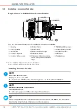
Preparations prior to installation of corner lat tube
y ≥ 250
≥ 120
≥ 260
≥ 350
5
15 ≤ z ≤ 35
30
2
1
3
4
5
7
6
8
9
14
12
11
15
10
13
Fig. 25:
Overview of dimensions for installation of Corner 400 lat tube
1 Masonry
6 Window frame
11 Flat tube sliding sleeve
2 Interior plaster
7 Window sash
12 Wall mounting bracket
3 Wall sleeve
8 Plaster embrasure edge
13
Corner lat tube**
)
4 Inner cover panel
9 Embrasure lattice
14 Insulation
5 Inner cover base plate
10
Protrusion of lat tube sliding
sleeve from plaster embrasure
edge
15 Sealing tape
**
)
Use corner 400 lat tube if (y + z) is min. 265 mm / max. 285 mm.
Use corner 500 lat tube if (y + z) is min 365 mm / max.
385 mm.
Installing the corner lat tube
noTe
formation of condensate.
Damage to the external wall!
► Incline corner lat tube with a fall at an angle of 1 – 2° to the window embrasure.
noTe
missing sealing tape on wall sleeve.
Reduced air low rate!
► Afix sealing tape around the outer edge of the wall sleeve.
TiP
Remove the protective discs from the wall sleeve on the interior and exterior wall side before
installing the corner lat tube. Otherwise no airlow is possible.
assembly anD insTallaTion


