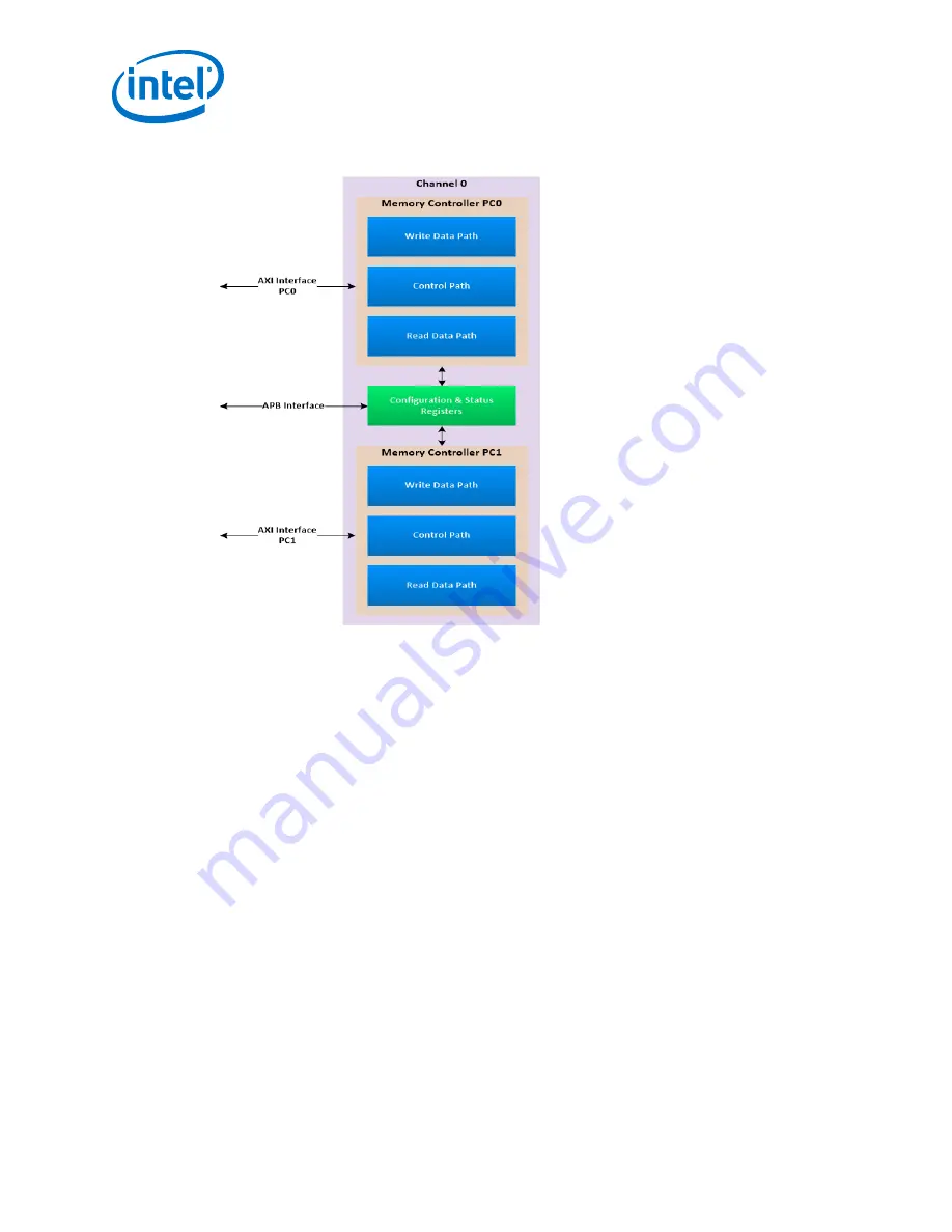
Figure 5.
Intel Stratix 10 MX HBM2 Controller Block Diagram
2.3.1 Intel Stratix 10 MX HBM2 Controller Details
This topic explains some of the high level HBM2 controller features.
HBM2 burst transactions
The HBM2 controller supports only the Pseudo Channel mode of accessing the HBM2
device; consequently, it can only support BL4 transactions to the DRAM. For improving
efficiency, it supports the pseudo-BL8 mode, which helps to provide two back-to-back
BL4 data using a given start address, similar to a BL8 transaction.
Each BL4 transaction corresponds to 4*64 bits or 32 bytes and a BL8 transaction
corresponds to 64 bytes per Pseudo Channel. You can select the burst transaction
mode (32 B vs 64B) through the parameter editor.
The user logic can interface to a maximum of 16 Pseudo Channels (16 AXI ports) per
HBM2 interface. Each AXI port has a separate write and read interface, and can handle
write and read requests concurrently at the same clock. Each write and read data
interface per AXI port is 128 bits wide.
User interface vs HBM2 Interface Frequency
The user interface runs at a frequency lower than the HBM2 interface; the maximum
interface frequency depends on the chosen device speed grade and the FPGA core
logic frequency. The rate-matching FIFOs within the UIB subsystem handle the data
transfer between the two clock domains.
2 Intel Stratix 10 MX HBM2 Architecture
UG-20031 | December 2017
Intel
®
Stratix
®
10 MX HBM2 IP User Guide
10


