Omni Installation Instructions
Page 48
© Mass Electronics Pty Ltd 2017
Edition 1.2 dated 20.08.2018
3-4.5.2 RS-485 Comms
The Omni U10 Comms Inputs provide the capability to connect to the host Omni controller and other
daisy-chained U10 REMs.
Connecting U10 REMs
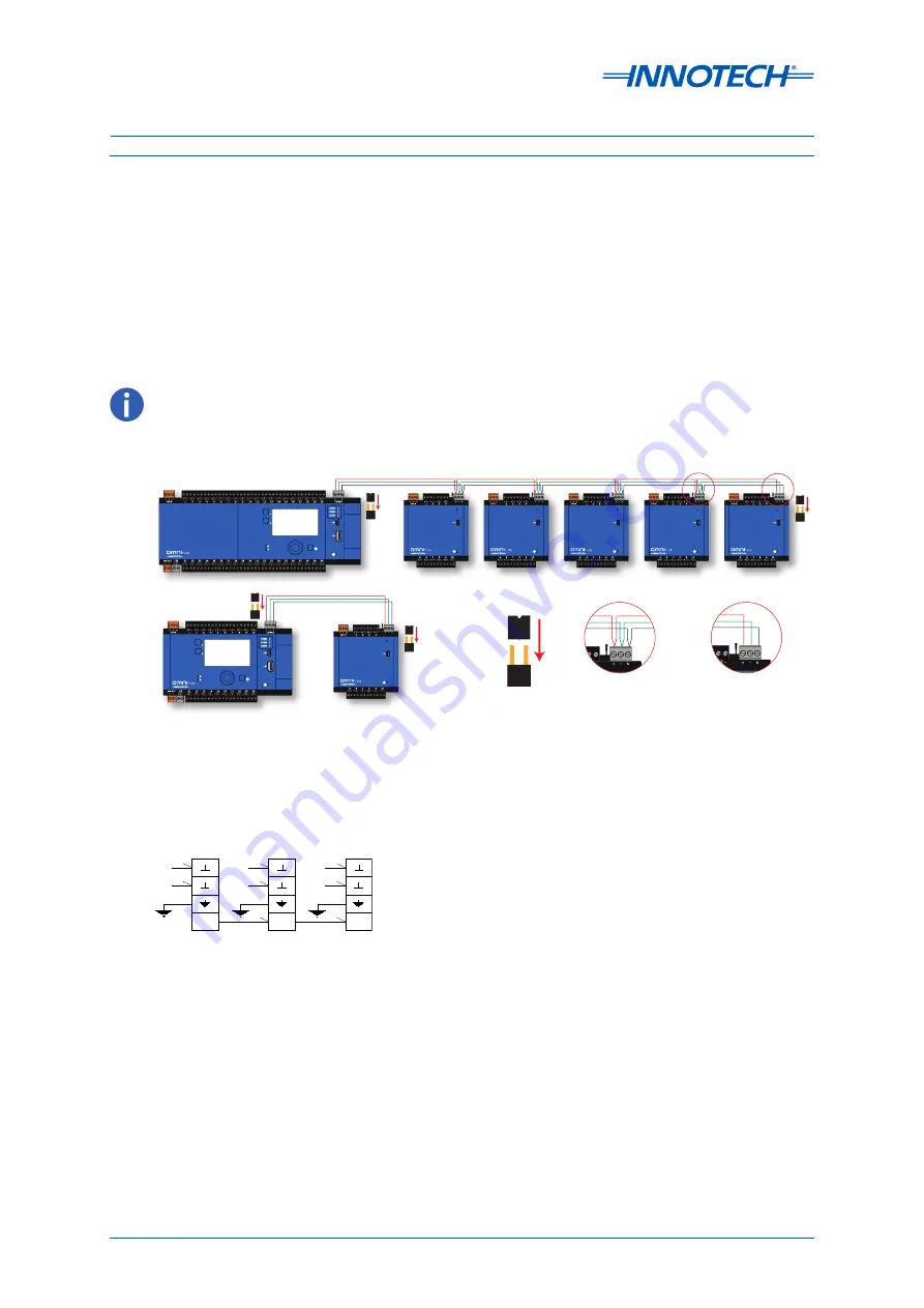
Omni U10 REMs are connected to the Omni network via the RS-485 Comms port(s). Connection is
achieved using daisy-chaining. The first U10 is connected to a Comms port on the host C40 or C20. For
subsequent U10 REMs using an Omni controller host, the cable termination for the next U10 is done
within the same terminal connector. When the last controller is connected, ensure to set the EOL
Jumper to the correct position.
Figure 3-10:
U10 Connection to Omni
COMMS
COMMS
COMMS
COMMS
COMMS
COMMS
COMMS
COMMS
COMMS
COMMS
COMMS
COMMS
U10 REMs are daisy
chained for connection
via the RS485 Comms.
COMMS
COMMS
U10 REM final connection.
Remember to set the End Of
Line (EOL) jumper on the first
and last device on the RS-485
network.
COMMS
COMMS
C40
C20
Place the jumper on
to set End of Line.
EOL Note:
In this example, the C20 and it’s REM require EOL jumpers to be set.
The C40 and the last REM require EOL jumpers to be set.
• An Omni C20 & C40 can support up to 5 daisy-chained U10 REMs. The Omni C14 does not support the U10 REM.
• EOL Jumpers are accessed inside the expansion bay on all controllers.
Omni C40 U10 Wiring
24V
0V
U10
RS485
Comms
24V
0V
U10*
RS485
Comms
24V
0V
Omni C40*
RS485
Comms
*Set the EOL jumper for the first and final RS-485 device
Figure 3-11:
Omni C40 U10 Connection
Summary of Contents for Omni C14
Page 1: ...Omni INSTALLATION INSTRUCTIONS...
Page 11: ...Omni INSTALLATION INSTRUCTIONS Preliminary Information 1...
Page 17: ...Omni INSTALLATION INSTRUCTIONS Mechanical Installation 2...
Page 31: ...Omni INSTALLATION INSTRUCTIONS Electrical Installation 3...
Page 53: ...Omni INSTALLATION INSTRUCTIONS Networking 4...
Page 74: ...Omni INSTALLATION INSTRUCTIONS Commissioning 5...


