


47
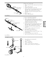
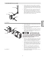
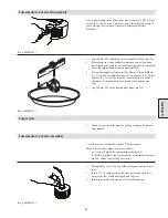
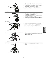
8.
Use two 7/16 - 20 x 1 inch capscrews and thread them into the
two threaded holes in the end cover (33).
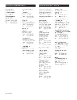
9.
Tighten both capscrews evenly until seal between the cover
(33) and drum (27) is broken, remove cover (33) and thrust
washer (36).
(Dwg. MHP1182)
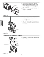
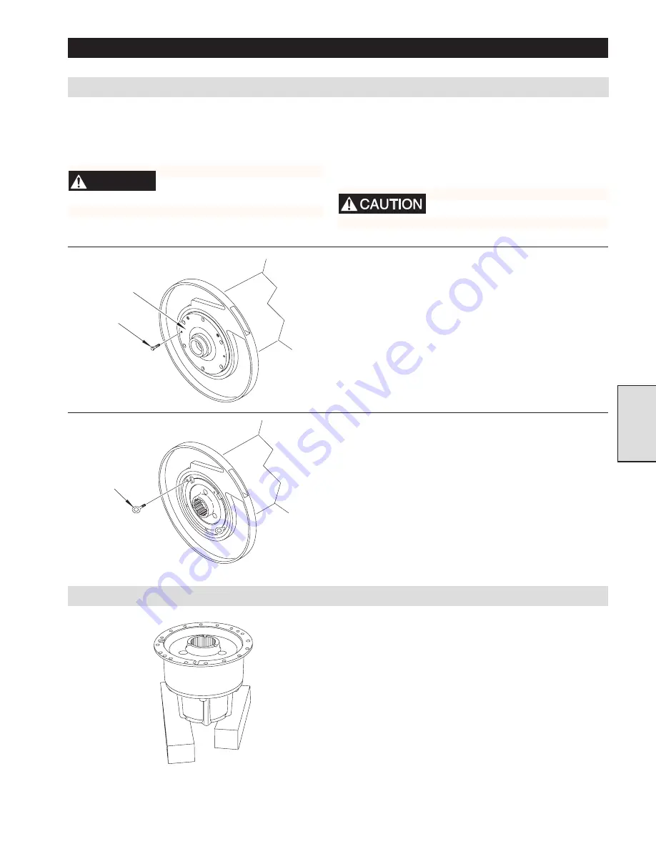
10. Use two 1/2 - 13 x 1 inch eye bolts and thread them into the
two threaded holes in housing (44).
11. Tighten both eyebolts evenly until seal between housing and
drum is broken.
12. Attach a suitable lifting device to the eye bolts and carefully
pull reduction gear assembly out of drum. Move to a clean
sturdy workbench.
(Dwg. MHP1183)
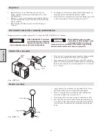
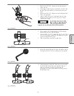
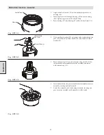
Reduction Gearbox Disassembly
1.
Support the housing assembly on two blocks.
(Dwg. MHP1167)
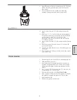
Reduction Gearbox Removal
Section 5
REDUCTION GEAR MAINTENANCE
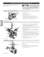
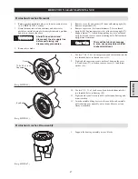
1.
Rotate gearbox until drain plug is in lowest position (refer
to “LUBRICATION” Section).
2.
Drain lubricant into a clean container and observe for
particles or metal shavings which might indicate a problem
and help to identify the cause.
WARNING
Shutoff, bleed down and
disconnect the air supply line
before performing any
disassembly procedures.
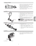
3.
Remove disc brake.
4.
Remove cover (4) and gasket (19) from outboard upright (26).
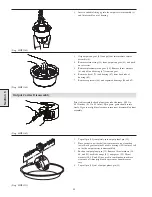
5.
Remove output shaft (28).
6.
Remove capscrews (86) from sideframes (78) at outboard
upright (26). Loosen capscrews (86) at the motor upright (27).
7.
Support drum (77). Attach lifting/pulling device to outboard
upright (26) and remove winch mounting bolts. Pull outboard
upright free from drum.
There will be lubricant seepage
in area, use appropriate material
to absorb lubricant.
Eye Bolt
7/16 x 20 x 1 inch
Capscrew
Cover
Summary of Contents for FA5A
Page 10: ...10 DISC BRAKE PARTS DRAWING Dwg MHP0667 Dwg MHP0630 One Way Clutch Detail Section 1...
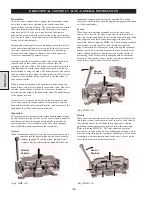
Page 19: ...19 Section 2 SERVICE NOTES...
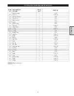
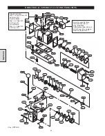
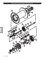
Page 54: ...54 REDUCTION GEAR ASSEMBLY PARTS DRAWING Dwg MHP1221 Section 5...
Page 57: ...57 SERVICE NOTES...
Page 58: ...58 SERVICE NOTES...
Page 59: ...59 SERVICE NOTES...


