


37
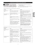
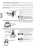
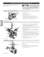
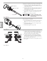
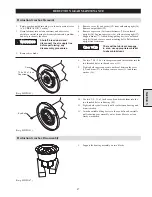
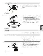
Starting at front of the valve body.
4.
Remove cotter pin (414) from shaft (401) and take off washers
(434).
5.
Remove retainer ring (429).
6.
Pull poppet subassembly out of valve body.
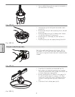
7.
Remove retainer (432) and seperate piston valve (431) from
inlet poppet, remove ‘O’ ring (430) from outside of valve
piston and ‘O’ ring (426) from inside of valve piston.
8.
Seperate poppet seat (428) from inlet poppet and remove ‘O’
ring (427).
19. Remove spring (422).
10. Remove exhaust poppet (420).
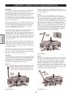
(Dwg. MHP1147)
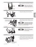
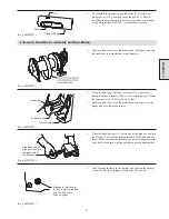
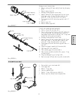
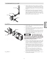
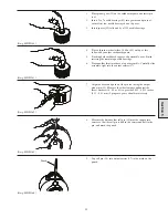
Turn the valve around and finish disassembly.
11. Remove roll pin (406) and shims (444).
12. Remove retainer ring (429). Remove shaft (401) with the rest
of the valve assembly. This step might require shaft (401)
being tapped from front end of valve body. The ‘O’ ring in the
restrictor seat (403) might create a tight fit.
13. Pull poppet subassembly out ot valve body.
14. Remove retainer (432) and seperate piston valve (431) from
inlet poppet, remove ‘O’ ring (430) from outside of valve
piston and ‘O’ ring (426) from inside of valve piston.
15. Seperate poppet seat (428) from inlet poppet and remove ‘O’
ring (427).
16. Separate inlet poppet assembly (423) from shaft (401).
17. Slide spring (422) off of shaft (401).
18. Slide restrictor poppet (402) off shaft (401).
19. Slide restrictor seat (403) off of shaft (401), remove ‘O’ ring
(404) and discard.
20. Using a suitable punch, tap out roll pins (405).
21. Back off setscrew (407) and slide sleeve (408) off shaft (401).
(Dwg. MHP1148)
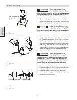
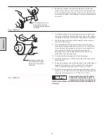
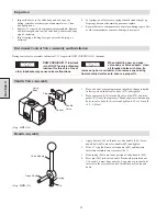
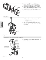
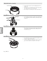
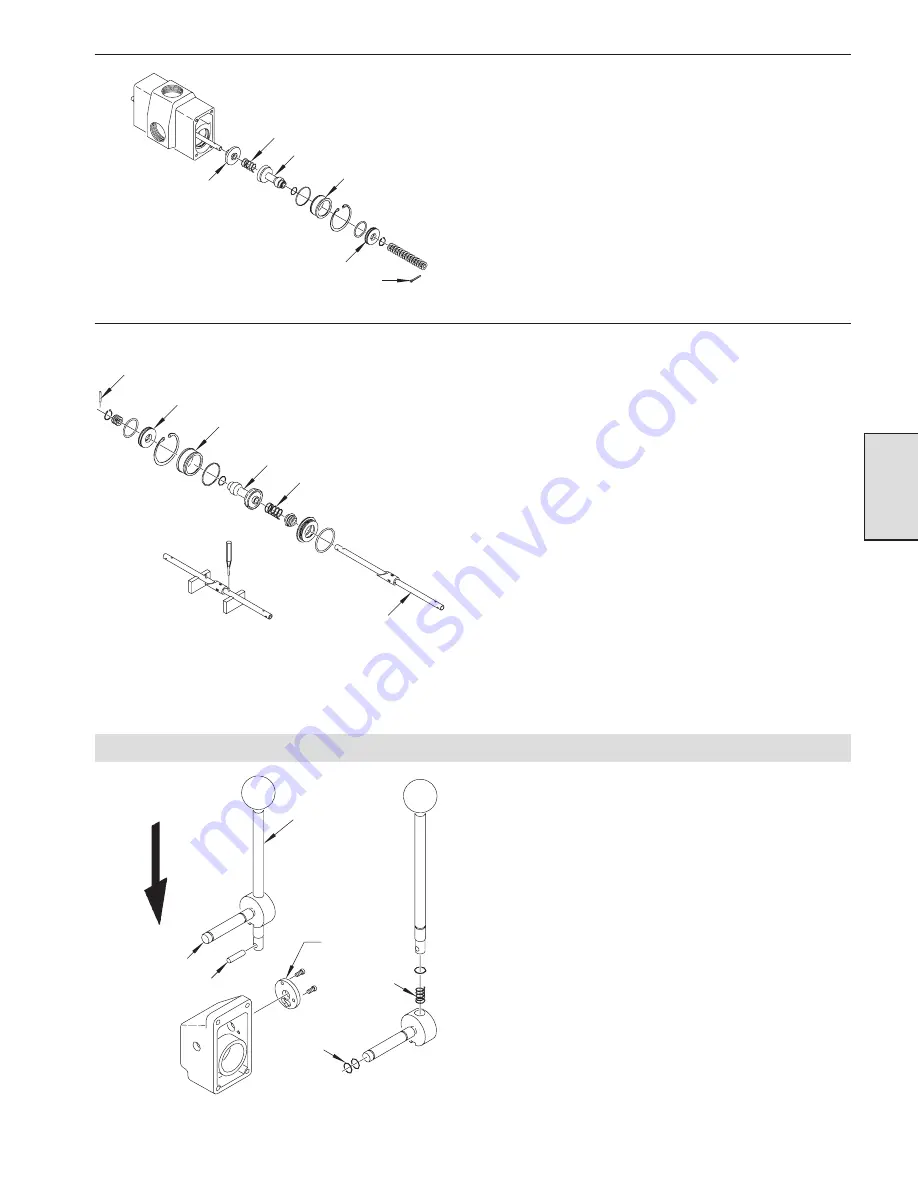
Handle Disassembly
1.
Push pin (463) out of valve handle (449).
2.
Catch spring (462).
3.
Remove ‘O’ ring (460).
4.
Unscrew handle ball (469).
5.
Remove ‘O’ rings (448) from cross shaft (461).
6.
Remove capscrews (465) and then detent plate (464).
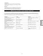
(Dwg. MHP1149)
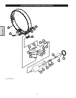
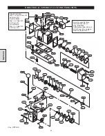
Section 4
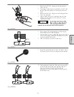
Exhaust Poppet
Spring
Inlet Poppet Assembly
Poppet Seat
Valve Piston
Cotter Pin
Roll Pin
Valve Piston
Poppet Seat
Inlet Poppet Assembly
Spring
Valve Shaft
Valve Handle
Cross Shaft
Pin
Detent Plate
Spring
‘O’ Rings
Summary of Contents for FA5A
Page 10: ...10 DISC BRAKE PARTS DRAWING Dwg MHP0667 Dwg MHP0630 One Way Clutch Detail Section 1...
Page 19: ...19 Section 2 SERVICE NOTES...
Page 54: ...54 REDUCTION GEAR ASSEMBLY PARTS DRAWING Dwg MHP1221 Section 5...
Page 57: ...57 SERVICE NOTES...
Page 58: ...58 SERVICE NOTES...
Page 59: ...59 SERVICE NOTES...


