


42
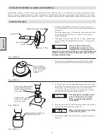
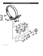
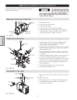
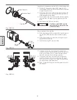
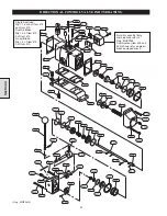
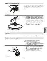
10. Insert capscrews (437) and washers (433) through top
mounting holes in valve cap (438). Place gasket (411) on
capscrews, insert these into valve body and loosely tighten.
11. Insert capscrews (439) and washers (433) through bottom
mounting holes. Tighten capscrews (437 and 439) to 54 to 60
inch lbs. (20 to 22 Nm).
12. Place pipe thread sealent on the threads of plug (436), insert
into valve cap (438) and tighten.
(Dwg. MHP1158)
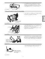
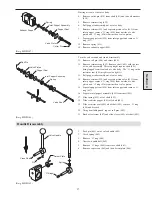
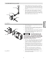
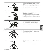
13. Insert capscrews (442) and flatwashers (434) into adapter
(440). These capscrews cannot be removed without:
a.
Removing end caps or,
b.
Removing adapter from valve body.
14. Apply Loctite
®
242 on threads of capscrews (441). Install
capscrews through adapter (440) and gasket (424). Insert these
into mounting holes in valve body and tighten to 13 to 17 ft lbs
(58 to 76 Nm).
(Dwg. MHP1159)
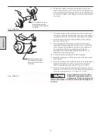
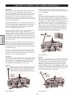
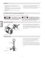
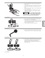
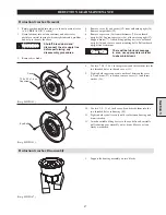
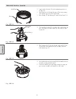
Brake Release Valve Installation and Adjustment
1.
Press brake valve (413) into valve body. Brake valve has one
end that is longer. This end should be down (in the valve
body).
Section 4
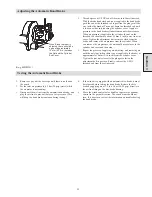
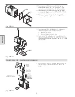
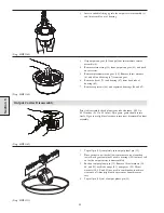
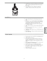
Plug
Gasket
Valve
Cap
Adapter
(Dwg. MHP1227)
Summary of Contents for FA5A
Page 10: ...10 DISC BRAKE PARTS DRAWING Dwg MHP0667 Dwg MHP0630 One Way Clutch Detail Section 1...
Page 19: ...19 Section 2 SERVICE NOTES...
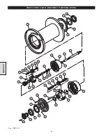
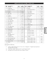
Page 54: ...54 REDUCTION GEAR ASSEMBLY PARTS DRAWING Dwg MHP1221 Section 5...
Page 57: ...57 SERVICE NOTES...
Page 58: ...58 SERVICE NOTES...
Page 59: ...59 SERVICE NOTES...


