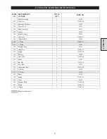


39
Valve Body Assembly
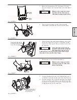
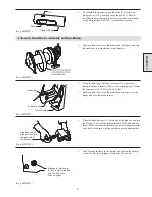
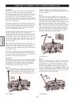
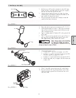
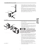
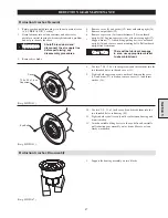
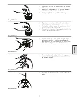
1.
Insert setscrew (407) into the center hole in shaft (401) from
bottom position. Center threaded hole is offset 18° (degrees)
from the two other holes and flats on shaft.
2.
With the flats on shaft (401) facing you, slide sleeve (408)
onto shaft (401). The flat part of the sleeve should be on the
right with the 45º (degrees) on the left.
3.
Press roll pins (405) into shaft (401) until pins are exposed
equally on both sides of the shaft.
(Dwg. MHP1022)
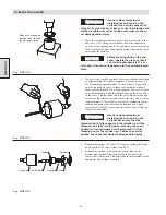
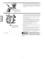
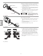
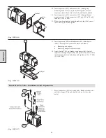
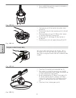
4.
Ensure that inlet poppet is at room temperature 70° F (21° C).
5.
Clean both inlet poppet (423) and ‘O’ ring with a non-residue
cleaner. Electrical contact cleaner works well, blow dry with
clean, dry compressed air.
6.
Apply a continuous bead of Loctite
®
4212 to the groove in the
inlet poppet.
7.
Slide ‘O’ ring over inlet poppet and into the groove. Press ‘O’
ring into groove all around and wipe excess Loctite
®
4212
from poppet surface. Allow Loctite
®
4212 to cure.
Wear rubber gloves while installing
‘O’ rings. The cleaner can cause
skin irritation. Loctite
®
4212 is very
sticky and hard to clean off skin.
(Dwg. MHP1152)
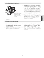
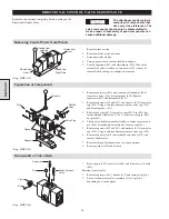
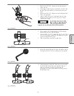
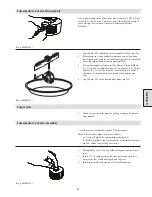
8.
Assemble both poppet valves.
a.
Lubricate the ‘O’ ring on the inlet poppet valve (423).
b.
Lubricate ‘O’ ring (427) and place it on poppet seat (428).
Place this assembly on poppet valve (423).
c.
Lubricate ‘O’ ring (426) and place on poppet valve (423).
d.
Install valve piston (431) on poppet valve and secure with
retainer (432).
(Dwg. MHP1153)
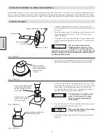
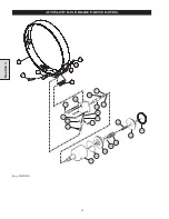
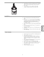
9.
Place ‘O’ ring (404) onto restrictor seat (403) and lubricate.
10. Insert restrictor seat (403) up through bottom of valve body
and into inner bore position. Press restrictor seat into valve
body until seated.
(Dwg. MHP1023)
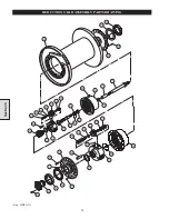
Section 4
Valve Shaft
Loctite
®
‘O’ Ring
‘O’ Ring
Restrictor
Seat
Summary of Contents for FA5A
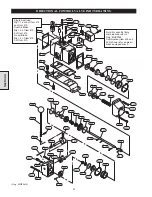
Page 10: ...10 DISC BRAKE PARTS DRAWING Dwg MHP0667 Dwg MHP0630 One Way Clutch Detail Section 1...
Page 19: ...19 Section 2 SERVICE NOTES...
Page 54: ...54 REDUCTION GEAR ASSEMBLY PARTS DRAWING Dwg MHP1221 Section 5...
Page 57: ...57 SERVICE NOTES...
Page 58: ...58 SERVICE NOTES...
Page 59: ...59 SERVICE NOTES...


