
8
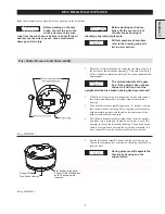
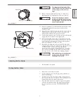
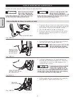
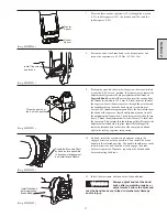
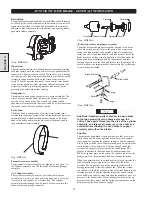
5.
Install the retainer ring (25) that holds the inner race in
position.
(Dwg. MHP0845)
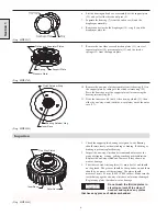
6.
Position the support plate with the spring pockets facing up.
Place the springs (21) into the pockets, and rest the pressure
plate (12) on top of the springs with the stepped side of the
pressure plate facing away from the springs.
(Dwg. MHP0839)
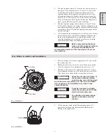
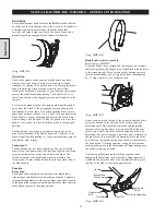
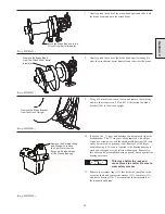
7.
Coat the friction (13) and separator plates (14) with oil.
Starting with one of the steel separator plates, alternately place
the separator and friction plates over the outer race.
(Dwg. MHP0847)
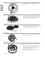
8.
Use the loose dowel pins (8) to help line up the three notches
on the steel separator plates.
(Dwg. MHP0849)
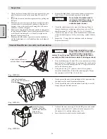
9.
Place a new gasket (19) on the mating surface of the support
plate.
10. Set the disc brake housing (7) on its side, and slip the three
dowel pins (8) through the holes provided. Wrap an elastic
band around the dowel pins (on the shallow side of the disc
brake housing) to hold them in position.
11. Set the disc brake housing down over the plates, shallow side
up. Ensure the bolt holes are aligned.
(Dwg. MHP1120)
Section 1
Bearing Retainer Ring
Inner Race
Clutch Retainer Ring
Pressure Plate
Spring
in pocket
Support Plate
Alternate the seperator
and friction plates
Elastic Band
Summary of Contents for FA5A
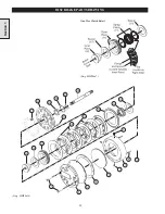
Page 10: ...10 DISC BRAKE PARTS DRAWING Dwg MHP0667 Dwg MHP0630 One Way Clutch Detail Section 1...
Page 19: ...19 Section 2 SERVICE NOTES...
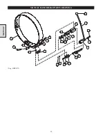
Page 54: ...54 REDUCTION GEAR ASSEMBLY PARTS DRAWING Dwg MHP1221 Section 5...
Page 57: ...57 SERVICE NOTES...
Page 58: ...58 SERVICE NOTES...
Page 59: ...59 SERVICE NOTES...


