


18
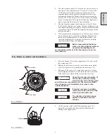
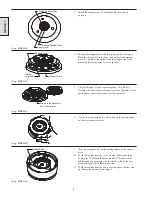
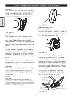
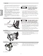
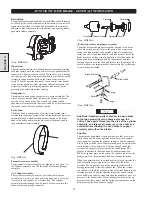
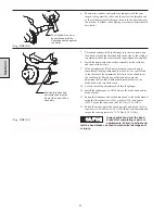
Adjusting the Manual Band Brake
Section 2
1.
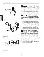
Place the band brake handle in a completely released
position. Take up some of the slack in the brake band by
turning the adjustment bolt, and then tighten the locking
capscrew to prevent the adjustment bolt from moving.
2.
Move the control handle towards the engaged position. The
handle should encounter growing resistance starting at
about the last third of its travel. The resistance should not
be enough to stop the handle from going “over-center” at
the end of its travel. Make sure the handle does not contact
the air motor adapter before it goes fully over-center. For
maximum load holding capacity, the handle should just
“over-center” before it touches the motor adapter. If it
“over-centers” too soon, the brake holding capacity will be
diminished. If it does over-center too soon, reposition it on
the splined eccentric shaft and readjust the brake.
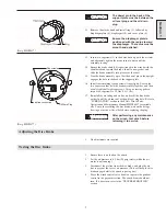
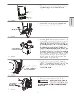
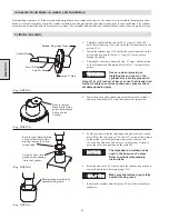
3.
The force needed to move the handle “over-center” should be
about 13.5 kg (30 lbs). If the handle cannot go “over-center,”
or if there is excessive resistance, reduce the tension by turning
the adjustment bolt in the counterclockwise direction. There
must be slack in the band brake when the handle is in the
released position. Always test the band brake before use.
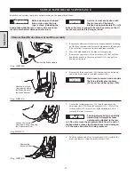
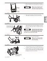
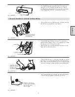
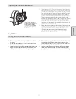
Testing the Manual Band Brake
1.
Remove any load from the winch, or if possible remove the
wire rope. If there is wire rope on the winch, this test may
cause it to unspool.
2.
Set the inlet air pressure to 6.3 bar (90 psig) static (while
the air motor is not running).
3.
If the winch is equipped with an automatic disc or band
brake, it must be disengaged before testing the band brake.
Disconnect the air line from the automatic disc or band
brake, and plug it to prevent loss of air pressure. Apply and
hold air pressure from an external source 3.5 to 6.3 bar (50
to 90 psig) directly to the air line fitting on the automatic
disc or band brake while testing the manual band brake.
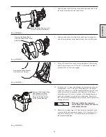
4.
Move the brake handle towards the winch until it goes fully
“over-center.”
5.
Move the winch control valve handle or operate the pendant
control in the payout direction. The winch drum should not
turn. If it does turn, review the information on troubleshooting
the manual band brake.
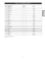
Summary of Contents for FA5A
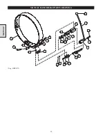
Page 10: ...10 DISC BRAKE PARTS DRAWING Dwg MHP0667 Dwg MHP0630 One Way Clutch Detail Section 1...
Page 19: ...19 Section 2 SERVICE NOTES...
Page 54: ...54 REDUCTION GEAR ASSEMBLY PARTS DRAWING Dwg MHP1221 Section 5...
Page 57: ...57 SERVICE NOTES...
Page 58: ...58 SERVICE NOTES...
Page 59: ...59 SERVICE NOTES...


