background image

LP630 Service Manual 


61   

Upgrade the software 

To upgrade the LP630 software, you need a 

null-modem cable

, available at your local computer or 

electronics retailer. You also need to download the software (page 58) and install the software on your 

computer (page 60). 

These instructions use the original software version. Later versions of software may become available. 

While the instructions steps will be the same, the software file names will change and not match the file 

names given here. Be sure to use the latest available software and select the latest file names when 

following these instructions. 

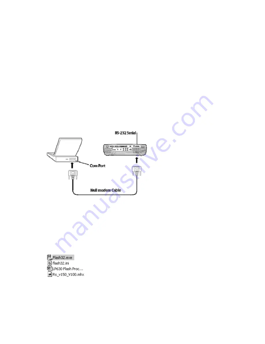
Connect the projector to the computer with a null-modem cable. 

Connect the RS-232 null-modem cable (9-Pin Female to 9-Pin Female) between the serial port 

on the projector and a computer serial port (often labeled as COM1). 

Many desktop computers have two or more serial ports. You can use these other ports if COM1 

has another device connected to it.  


Unplug the AC power cord from the projector. The upgrade process starts 

without

 power to the 

projector. 

Now you're ready to upgrade the software. 

Upgrade the software  

In Windows Explorer, locate the extracted files (C:/LP630/v1.0). Then double-click the file named 

Flash32.exe. 


The Flash32 dialog box appears. 

Do one of the following:  

If you connected the null modem cable to the COM1 port on the computer, go to step 4. 

—Or— 

Summary of Contents for LP630

Page 1: ...Service Guide for the LP630 010 0331 00 ...

Page 2: ... time Measure the AC voltage across the combina tion of 1500ohm resistor and 0 15 µF capacitor Reverse the AC plug at the AC outlet and repeat AC voltage mea surements for each exposed metallic part Voltage mea sured must not exceed 5 25V rms This corresponds to 3 5 mA AC Any value exceeding this limit consti tutes a potential shock hazard and must be corrected immediately PRODUCT SAFETY NOTICE Ma...

Page 3: ...ce the Safety Interlock Switch 30 Remove and Replace the Lamp Door Latch 31 Remove and Replace the Front and Rear IR ECAs 33 Remove and Replace the Optical Engine 34 Remove and Replace the I O Assembly 38 Removing and Replacing the Ballast 41 Remove and Replace the Elevator 44 Remove and Replace the Power Supply 46 Remove and Replace the Intake Duct and Intake Fans 50 Remove and Replace the Lamp F...

Page 4: ...shuts down 73 Dim image 74 Any image problem 75 Keypad problems 75 Keypad problems 76 Menu problems 77 Remote problems 78 Audio problems 79 Checking voltages on the controller ECA 80 Block diagram 81 Parts Lists 82 FRUs by Numeric Listing 82 FRUs by Alphabetic Listing 84 Standard Accessories 86 ...

Page 5: ... harmful interference to radio communications Operation of this equipment in a residential area is likely to cause harmful interference in which case the user will be required to correct the interference at his own expense WARNING Changes or modifications made to this equipment not expressly approved by Toshiba or parties authorized by Toshiba could void the user s authority to operate the equipme...

Page 6: ...n of the product and to protect it from overheating and these openings must not be blocked or covered The openings should never be blocked by placing the product on a bed sofa rug or other similar surface This product should not be placed in a built in installation such as a bookcase or rack unless proper ventilation is provided or the manufacturer s instructions have been adhered to IMPORTANT SAF...

Page 7: ...exity of the repair Find the FRU you wish to replace and then find the path from Start to see which parts you must remove to access it Top Case Front and Rear IR ECAs Exhaust Fan Controller ECA Optical Engine Power Supply Ballast I O Assembly Speakers Rear Bezel Lamp Fan Handle Zoom and Focus Rings Projection Lens Lamp Door Detection Switch Intake Duct Intake Fans Elevator I O ECA Bottom Case Leve...

Page 8: ...lowing easy access to the lamp when the projector is mounted on the ceiling The lamp SP Lamp LP630 fits in the lamp housing in the optical engine CAUTION Allow the lamp to cool for at least 30 minutes before removing it 1 Slide the lamp door off of the top case 2 Loosen the two captive screws that fasten the lamp to the lamp housing ...

Page 9: ...LP630 Service Manual 9 3 Grasp the two handles on the lamp and pull it out of the lamp housing ...

Page 10: ...ted on the outside of the bottom case 1 Place the projector upside down on the work surface 2 Pull the filter out of its slot on the bottom case 3 To clean the filter use a vacuum or compressed air to blow out dust on the filter element Do not blow the filter while holding it close to the projector ...

Page 11: ...nother identical rubber foot fastens to the end of the elevator shaft Replace the leveling foot 1 Place the projector upside down on the work surface Rotate the foot counter clockwise until the foot and its attached shaft detach from the projector Note that a section of the shaft is not threaded When you replace the foot turn the shaft clockwise until it reaches the non threaded area Then start th...

Page 12: ...down on the work surface Note that the rubber foot on the bottom case and the elevator are identical 2 Remove the black M3x10 Phillips screw that fastens the rubber foot to the bottom case or to the elevator shaft 3 When you replace the rubber foot do not over tighten the screw ...

Page 13: ... indicates that the lamp door is in place 1 Turn the projector on its side Then use a 1 Phillips screwdriver to remove the five 4x10 self tapping screws from the recessed openings on the bottom case 2 Place the projector on its bottom Use a 1 Phillips screwdriver to remove the two black 3x8 screws from the rear of the projector ...

Page 14: ...e rear of the case clear the I O connectors Then lift the projection lens side of the top case As you lift you will see the keypad and IR cables that to the top cover from the main controller ECA 4 Lift the tab on the ZIF connector holding the blue ribbon cable then gently pull the ribbon cable from the connector ...

Page 15: ...ug the interlock cable from its connector on the controller ECA Assembly Notes Before attaching the top case to the projector make sure that all the cables are correctly seated and that there are no missing screws or rattling parts ...

Page 16: ... part of the optical engine controller set 525 0038 00 The engine and controller are matched for optimum image quality and must be replaced together 1 Remove the top case see page 13 2 Detach the red green and blue LCD ribbon cables from their ZIF connectors To do this gently pry up the locks on the three ZIF connectors at the center of the controller ECA Then gently pull the ribbons free of the c...

Page 17: ... or reseating the ribbon cables The hinges on the locks are extremely delicate and break easily If you break a connector you must replace the controller ECA 3 Use a 1 Phillips screwdriver to remove the seven M3x6 screws from the front of the controller ECA ...

Page 18: ... 4 Unplug the following cables from the controller ECA NOTE To unplug the controller power supply connector you need to lift the corner of the controller ECA slightly so that the edge of the connector clears the lamp housing ...

Page 19: ...r of the controller to unplug the interface ECA controller ECA connector The connector is located beneath the controller ECA near the center 6 As you lift the controller off of the projector pull the rear IR cable out from beneath the speaker bracket ...

Page 20: ... the bottom of the controller ECA 2 Plug in the controller power supply connector The connector is located on the corner adjacent to the lamp housing 3 Align the controller ECA as show below Then press it into place When the controller is aligned properly the interface controller connector engages 4 Secure the controller to the projector with the seven M3x6 screws ...

Page 21: ...LP630 Service Manual 21 5 Plug in and route all cables as shown below a The power supply side of the controller ...

Page 22: ...LP630 Service Manual 22 b The projection lens side of the controller ...

Page 23: ...LP630 Service Manual 23 c The front of the controller ...

Page 24: ... work the cable into the connector Ensure that the gold contact side faces upward and the cable is fully inserted See the illustration below To close the latch press the middle of the latch with your finger until it closes CAUTION Take care when opening and closing the latches on the ZIF connectors The latches are very delicate ...

Page 25: ...emove and Replace the Handle The handle 340 0912 00 is located on the projection lens side of the projector It inserts into two slots in the bottom case 1 Remove the top case see page 13 2 Lift the handle out of the bottom case ...

Page 26: ...mplete exhaust fan assembly 526 0104 xx which includes the fan the ducting and the thermal switch 1 Remove the top case 2 Unplug the exhaust fan thermal switch and lamp fuse cables from their connectors on the controller ECA Lift the cable clip adjacent to the controller ECA to release the cables 3 Use a 1 Phillips screwdriver to remove the two 3x8 self tapping screws that fasten the base of the f...

Page 27: ...e exhaust fan to the duct Then separate the two parts Assembly Notes If you are replacing only the exhaust fan make sure the label in the center of the fan faces the duct Make sure the cable emerges as it does in the illustration in step 4 above When you replace the assembly be sure you route the cables properly See step 2 above for information ...

Page 28: ...rately 1 Remove the top case see page 13 2 The keypad adheres to the outside of case with a layer of adhesive Use a screwdriver to press against the keypad from inside of the top case Once the keypad is separated from the top case slide a flat head screwdriver beneath the edge of the keypad from the top Carefully separate the keypad from the well in the top of the case ...

Page 29: ...e allowing the keypad cable to slide through and out of the slot Assembly Notes Make sure to route the keypad cable through the slot in the top case Avoid kinking the cable Lay the keypad into the recess in the top case and press to secure the keypad to the top case Apply adhesive tape to the ribbon near the slot to ensure proper positioning of the cable ...

Page 30: ... The safety interlock switch attaches to the top case and connects to the controller ECA with a short twisted pair cable 1 Remove the top case see page 13 and lamp door see page 8 2 Gently pry the tab on the top case away from the switch Then lift the switch out from beneath the mounting lip in the top case Assembly Notes Make sure the switch is properly seated and that the switch arm is in the pr...

Page 31: ...se but may be ordered separately 1 Remove the top case see page 13 2 On the inside of the top case remove the M3x8 self tapping Phillips screw that fastens the lamp door latch retainer to the top case Press on the retainer while you loosen the screw Then lift the latch and spring out of the top case Assembly Notes When you replace the latch you need to hold the spring down with a bladed screwdrive...

Page 32: ...ual 32 The retainer has two tabs that fit into two slots in the top case While holding the spring down insert the tabs into the slots and lower the retainer into place Hold the retainer down while you replace the screw ...

Page 33: ...ector in the center adjacent to the lens The other is fastened to the rear corner of the controller ECA The IR ECA do not include the cables that plug into the controller ECA 1 Remove the top case see page 13 2 Unplug the cable from the connector on the IR ECA and then remove the single M3x6 screw that is holding the remote control ECA in place Front Remote ECA Rear Remote ECA ...

Page 34: ...projector is in use Avoid touching any portion of the lamp module that is located in the light path Oils from your fingers can cause smudges and uneven heating of lamp surfaces resulting in decreased image quality and premature lamp failure If the lamp is ruptured or the lamp module is cracked or damaged be careful of quartz or glass fragments that could cause personal injury 1 Remove the followin...

Page 35: ...move the two M3x8 self tapping screws with captive washers that fasten the lamp power cable to the lamp housing Lift the cable up and away from the lamp housing 5 Unplug the lamp sensor cable from the connector on the lamp housing ...

Page 36: ...the four M4x10 self tapping screws that fasten the engine to the case bottom 7 Unwrap the black thermal switch cable from around the engine fan cables 8 Lift the optical engine out of the bottom case Note that the engine fan cable is still attached to the projector ...

Page 37: ...gine inside the bottom case make sure that the lamp power connector is in place and that the engine fan cable emerges from between the engine and power supply Make sure the engine seats properly There are registration pins that fit into holes adjacent to the two outside screws Once the pins are in the holes the engine is properly seated Make sure that you properly route all cables See the illustra...

Page 38: ...e see page 13 Controller ECA see page 16 2 Remove the three M3x8 self tapping Phillips screws that fasten the interface assembly to the case bottom Then lift the assembly out of the projector The rear bezel stays with the assembly 3 Do one of the following Place the assembly aside and go to the part you want to remove next Or Follow the directions below to replace a rear bezel speaker or interface...

Page 39: ...ews that fastens the speaker to the interface bracket This screw anchors the speaker retainer 330 0773 xx to the back of the speaker holding the speaker in place The bottom of speaker is held in place with a tab on the interface bracket When you install a speaker orient the speaker so that the cable is at the bottom of the speaker See the illustration above ...

Page 40: ... leads from their connectors on the interface ECA Remove the three black M3x8 Phillips screws that fasten the interface ECA to the interface bracket from the bezel side Remove the four M3x8 Phillips screws that fasten the ECA to the bracket from the ECA side ...

Page 41: ...rom the ballast when the lamp strikes High voltage produced by the ballast to strike the lamp can ruin test instruments as well as cause personal injury 1 Remove the following items Top case see page 13 Controller ECA see page 16 Optical engine see page 34 2 Remove the three M3x8 self tapping Phillips screws that fasten the ballast to the bottom case Remove the one M3x6 machine screw that attaches...

Page 42: ...LP630 Service Manual 42 3 Lift the ballast from the bottom case 4 Unplug the cable that connects the ballast to the power supply ...

Page 43: ...e the registration pins in the bottom case fit into the holes adjacent to the front and rear screws Make sure you replace the cable retainers on the front screw and the machine screw on the top of the power supply Route the lamp cable under the cable retainer on the front screw ...

Page 44: ... the projector when you press the actuator button on the bottom case The elevator foot fits at the bottom of the shaft 1 Remove the following items Top case see page 13 Controller ECA see page 16 Optical engine see page 34 Intake duct see page 50 2 Adjust the elevator shaft to its fully extended position 3 Remove the Phillips screw in the bottom of the rubber foot 4 Remove the three M3x8 self tapp...

Page 45: ...LP630 Service Manual 45 5 Push in the elevator button through the hole to clear the case bottom 6 Draw the elevator shaft through the hole in the bottom case to remove the elevator assembly ...

Page 46: ...y attached cables One cable goes to the heat sensor located under the lamp housing The other goes to a power connector ECA at the rear of the projector 1 Remove the following items Top case see page 13 Controller ECA see page 16 Interface assembly see page 40 Optical engine see page 34 Ballast see page 41 2 Remove the three M3x8 self tapping Phillips screws that fasten the power supply to the bott...

Page 47: ... the two screws that fasten the power connector ECA to the bottom case Lift the edge of the ECA closest to the intake duct and slide the power connector out of its hole in the bottom case 4 Remove the screw that holds the heat sensor ...

Page 48: ...LP630 Service Manual 48 5 Lift the power supply from the bottom case ...

Page 49: ...y flex the bottom case to get the ECA to snap into place Note that a post in the bottom case also fits into a hole in the ECA When you install the power supply make sure the registration pins in the bottom case fit into their matching holes on the power supply When you fasten the heat sensor to the bottom case make sure to route the cable next to the tabs in the bottom case See step 4 above ...

Page 50: ...o the intake duct on both sides of the projection lens The intake duct routes the air through the intake filter in the bottom case 1 Remove the following items Top Case see page 13 Controller ECA see page 16 Optical Engine see page 34 2 Remove the three M3x8 self tapping Phillips screws that fasten the intake duct and fans to the bottom case 3 Lift the intake duct from the bottom case ...

Page 51: ...or both of the fans To do that first unwind the cables from the tabs on intake duct Then remove the two M3x35 self tapping Phillips screws that fasten the fan to the intake duct Both fans are identical Assembly Notes Carefully route the fan cables around the intake duct so that they are not pinched when the projector is reassembled ...

Page 52: ...LP630 Service Manual 52 ...

Page 53: ...e see page 13 Controller ECA see page 16 Optical engine see page 34 2 Place the optical engine upside down on the bench 3 Remove the two M3x20 self tapping Phillips screws that fasten the fan to the optical engine Before removing the fan note the cable routing Assembly Notes Route the fan cable behind the power supply and between the power supply and the ballast to be in the correct position for c...

Page 54: ...tion lens barrel with small machine screws 1 Remove the following items Top case see page 13 Controller ECA see page 16 Optical engine see page 34 2 Use a 00 Phillips screwdriver to remove the three M1 7x4 black machine screws from the rear of the zoom ring 3 Push back the zoom ring to reveal the three screws on the focus ring Use a 00 Phillips screwdriver to remove the three M1 7x4 black machine ...

Page 55: ...4 Remove the focus ring by pulling it forward over the end of the lens 5 Remove the zoom ring by pulling it forward over the end of the lens Assembly Note Do not over tighten the screws when you install the zoom and focus ring ...

Page 56: ...A see page 16 Optical engine see page 34 Zoom and focus rings see page 54 2 Using a 1 Phillips screwdriver remove the four M3x8 machine screws that attach the lens to the optical engine Set aside the four washers for assembly 3 Gently pull the lens away from the optical engine Assembly Notes Replace the washers over the screw holes on the optical engine before mounting the lens Align the three hol...

Page 57: ...fs elevator bottom feet and certification label 1 Remove the following items Top Case see page 13 Controller ECA see page 16 I O assembly see page 38 Ballast see page 41 Power supply see page 46 Optical engine see page 34 Front and rear IR ECAs see page 33 Intake duct and fans see page 50 You are left with the bottom case ...

Page 58: ...lick the Download Now button the File Download dialog box appears NOTE The illustrations below refer to version 1 0 of the LP630 system software The version of the software you download may be different 1 In the File Download box select Save This Program To Disk option then click OK ...

Page 59: ... you want to store the file then click OK The file downloads to your computer s hard drive Now you re ready to install the software on the computer You can also transfer the file to a floppy disk to use on other computers Go to installing the system software on the computer on page 60 ...

Page 60: ...tents The filename 630v10 exe means that this is version 1 0 of the system software for the LP630 The version number changes each time InFocus updates the software 3 The WinZip Self Extractor dialog box appears Leave the folder choice as c WinZip extracts the files to several locations NOTE If you can t find the file use the Windows Find feature to locate the file On the Tools menu point to Find t...

Page 61: ...se instructions Connect the projector to the computer with a null modem cable 1 Connect the RS 232 null modem cable 9 Pin Female to 9 Pin Female between the serial port on the projector and a computer serial port often labeled as COM1 Many desktop computers have two or more serial ports You can use these other ports if COM1 has another device connected to it 2 Unplug the AC power cord from the pro...

Page 62: ... the Config button In the Flash32 dialog box 3 In the Configuration dialog box select the computer port to which the null modem cable is connected Then click OK 4 In the Flash32 dialog box click the Select File button The Open dialog box appears 5 Select the Rs_v150_V100 mhx file then click OK ...

Page 63: ...utton on the projector While holding the Reset button down plug in the power cord to the projector When the keypad lights up immediately release the Reset button If the keypad is still lit after you have released the Reset button then the download is proceeding If the keypad is not lit after releasing the Reset button click the Stop button in the Flash32 dialog box disconnect the power cord and re...

Page 64: ...om the projector and close the Flash32 software Confirm the software upgrade 1 Plug the AC power cord into the projector then power it up 2 Press the menu button on the keypad to display the projector menus Then press the standby key until you select the status menu 3 Press the menu button again to display the status window The new software version appears n the Status window ...

Page 65: ...ret the version number in the example above The version number is really a list of the HEX files version numbers In the illustration above 10 boot code v1 0 13 ROM code v1 3 10 GUI code v1 0 13 data configuration v1 3 10 Splash screen version 1 0 ...

Page 66: ...ly produced video You ll need the video in DVD laser disc or video cassette format InFocus strongly suggests you use Video Essentials Optimizing Your Audio Video System DVD International 1997 This DVD is available at Amazon com Audio Video cables Use the cables that come with the projector including the Digital Video Interface DVI cable RGB test screens Use the Test Patterns available at the InFoc...

Page 67: ...le to the wall Verify that the elevator and leveling foot are functional Verify that the focus and zoom rings operate properly Verify cosmetics Composite video from video source On the keypad press the Video button Verify that the video automatically synchronizes Verify there is no distortion noise or other abnormalities Listen for audio quality Verify there is audio emitted from each speaker with...

Page 68: ... the 4 green squares After focusing on the green squares on the middle icon turn the zoom ring to make the largest image then repeat the focus tests Turn the Image Shift knob clockwise and counterclockwise Verify that all four corner icons have clear resolution Verify that the white space is visible on all 5 bar line icon areas between green Verify that the image focuses through the full zoom rang...

Page 69: ...ing columns or other general image abnormalities present On the keypad press Menu On the Display menu select Reset All Verify that the image synchronizes Power Down After all tests are complete turn the power off and disconnect all cables Attach the lens cap Verify unit is powered off before disconnecting cables ...

Page 70: ...p case and closed it with a piece of tape Important Troubleshooting Preliminaries For power up problems Make sure the power cord is good For image menu audio problems 1 Make sure source signal is compatible with projector 2 Make sure cables to projector are good 3 Do a reset all to get to factory default settings 4 Reflash software to ensure that the software is not scrambled ...

Page 71: ...ey presses Replace lamp door interlock switch in top case Dead No signs of power No LED no fans Use known good power cord Does projector power up Replace power cord no yes Does lamp door switch in top case sound good when actuated no yes no Does projector work with remote yes page 76 page 46 page 30 ...

Page 72: ...en goes out and fans run at full speed Note All fans are sensed to detect if they are running If one is not running the others will run at full speed and the lamp will not come on For any fan not visible sub a fan into the connector Are power supply voltages good Replace power supply Are lamp enable voltages good Replace controller ECA optical engine set Replace ballast yes no no yes There are fou...

Page 73: ...roblem because fans have a sensor line that prevents the projector from properly starting up The problem is almost always a power supply or controller ECA with a thermal breakdown problem Make sure the intake filter is not clogged with debris Replace the power supply and run projector long enough to know if that is the problem Is the problem solved No page 10 page 16 page 46 ...

Page 74: ...stitute an known good lamp It must be a used lamp or the lamp counter will be reset to zero hours Dim Image Image still dim Replace lamp Replace optical engine controller ECA set no yes Did you perform a reset all page 8 page 8 pages 16 34 ...

Page 75: ...oblem Missing distorted noisy rolling torn frozen repeated shifted ghosting or alignment Is it video only Replace I O ECA Replace optical engine controller ECA no yes Power supply voltages good Replace power supply no yes page 34 16 page 40 page 80 page 46 ...

Page 76: ... good controller ECA No Replace the keypad Yes Replace the controller ECA Yes Substitute a good keypad Does the projector respond to key presses No Replace the controller ECA Yes Replace the keypad Does the projector respond to key presses The controller ECA and optical engine must be replaced as a set page 16 page 28 page 28 page 16 page 28 page 16 ...

Page 77: ...r reflash the latest software into the projector Replace the controller ECA optical engine set Does the menu appear No Yes If the remote works and the keypad doesn t go to Keypad problems Try pressing the Menu button on both the remote and keypad If the keypad works and the remote doesn t go to Remote problems Yes page 78 pages 16 and 34 page 76 ...

Page 78: ... controller ECA optical engine set Infrared remote problem Does the remote work No Yes Replace the batteries Use known good batteries in the remote Use a known good remote with the projector Does the remote work No Yes Replace the remote page 16 and 34 ...

Page 79: ...LP630 Service Manual 79 Audio problems Replace I O ECA Audio problem Substitute speaker Speaker sound good Replace speaker no yes page 39 page 38 ...

Page 80: ... need to power up the projector with the top case removed To do this remove the top case see page 13 Then remove the interlock switch page 30 and plug the cable into its connector on the controller ECA Tape or clamp the switch shut You can power up the projector with the remote control ...

Page 81: ...LP630 Service Manual 81 Block diagram ...

Page 82: ...773 00 Speaker retainer One per speaker 340 0908 00 Zoom ring 340 0909 00 Focus ring 340 0910 00 Bottom case Includes elevator leveler and rating label 340 0911 00 Rubber foot Rear foot and elevator foot are identical 340 0912 00 Handle 340 0914 00 Intake duct Does not include engine fans 340 0915 xx Rear bezel 340 0930 00 Top case Includes safety interlock switch lamp door latch warning label key...

Page 83: ...093 00 Ballast 525 0038 00 Optical engine and controller ECA Set Cannot be ordered separately 526 0102 00 Lamp fan 526 0103 00 Intake fan Two intake fans fasten to the intake duct 526 0104 00 Exhaust fan assembly Includes thermal lead 526 0105 00 Exhaust fan Fan only 526 0106 00 Keypad Includes ribbon cable Part of top case 802 0028 00 LP630 fastener kit SP Lamp LP630 Lamp ...

Page 84: ...ntake duct 340 0914 xx Does not include fans Intake fan 526 0103 xx Two intake fans mount on the intake duct Intake filter 321 0179 xx I O ECA 510 1651 01 Also called the Interface ECA I O bracket 330 0772 xx Also called the interface bracket IR ECA 510 1606 xx The front and rear IR ECAs are identical IR cable front 211 0176 xx Lamp SP Lamp LP630 Lamp door 340 0931 xx Not included with top case La...

Page 85: ...ors Rear foot 328 0138 xx Safety interlock switch 215 0024 xx Speaker 232 0188 xx Speaker retainer 330 0773 xx One required for each speaker Thermal Switch 232 0189 xx Top case 340 0930 xx Includes lamp door interlock switch lamp cover latch warning label and keypad Warning label 020 1226 xx Zoom ring 340 0908 xx ...

Page 86: ... ft 1 8 m 210 0053 xx Computer Audio Cable 6 ft 1 8 m 210 0118 xx Ceiling Mount Lamp Door Label 020 1170 xx VESA HD15 Computer Cable 210 0119 xx Remote 590 0399 xx Online User s Guide CD ROM 010 0282 xx Regional Power Cord Part Number North American Power Cord 210 0023 xx Australian Power Cord 210 0027 xx UK Power Cord 210 0028 xx European Power Cord 210 0029 xx Danish Power Cord 210 0030 xx Swiss...

Reviews: