background image

11

  MASONRY 500

IMER INTERNATIONAL S.p.A.

GB

GB

15.3.1  CUTTING  WITH  CUTTING  WHEEL  LOWERED
FROM  ABOVE.

Adjust  the  vertical  height  by  turning  the  crank  (ref.11,  fig.1),
position the piece to be cut, start the panel saw and commence
cutting operations by pressing the pedal (ref.16, fig.1) to lower
the  wheel  from  above.

15.3.2  BLADE CHANGE

To change the blade refer to section 14.

16.  USING  550  DIAMETER  CUTTING  WHEEL.

If an optional cutting wheel diameter 550 mm is used instead of
the standard  wheel diameter  500  mm,  it is  important  that  the
stop  bolt  be  calibrated  to  prevent  interference  between  the
wheel and the carriage when the head is in the lowest position.

 - Warning. The panel saw is fitted with a stop bolt to

stop  the  cutting  wheel  in  the  lowest  vertical  position.
This  stop  is  calibrated  for  a  500  mm  cutting  wheel.    If
you  are  using  a  550  mm  cutting  wheel,  loosen  the  bolt
(ref.  17,  fig.  1),  lower  the  wheel  to  the  lowest  position,  by
turning  the  crank,  then  check,  with  the  motor  turned
off,  that  there  is  no  interference  between  the  cutting
wheel  and  the  piece  holder  carriage  when  the  pedal  is
pressed.    Adjust  the  bolt,  bring  it  into  contact  with  the
stop  and  tighten  the  lock  nut.

  -  Note that the blade must have an external diameter

of  550  mm,  a  central  hole  diameter  of  25.4  mm  and  max.
thickness  of  3  mm.

17.  MAINTENANCE

 -  WARNING!  Servicing  must  always  be  carried  out  by

qualified  technicians  and  only  after  the  motor  has  been
switched  off.

  -  Always  keep  the  guards  in  proper  working  order

and  free  from  damage.Take  particular  care  to  ensure
that  the  blade  guards  are  kept  efficient  and  clean,
replacing  them  if  they  are  damaged

  -  As  there  is  the  continuous  risk  of  inadvertent

damage  to  the  electric  cables,  these  must  be  checked
regularly  each  time  before  the  machine  is  used.

Do not leave the machine outside: it must always be protected
from  the  weather.
Below is a list of the cleaning operations that must be carried
out at the end of every shift.

17.1  TANK  CLEANING

Empty  the  tank  by  removing  the  drain  plug.  Remove  cutting
residue using a jet of water.

17.2  TANK  REMOVAL  (Ref.Fig.7).

Empty the drum opening the drum cap from right or left side.

17.3  WORK  SURFACE  CLEANING

Always  keep  work  surfaces  clean.  Residual  dirt  can  impair
cutting  precision.

17.4 GUIDE RAIL CLEANING

It is good practice to remove all traces of dirt from the guides.

17.5  CLEANING AND  MAINTENANCE OF  COOLING CIRCUIT

- If water does not reach the blade stop the machine immediately to
avoid blade damage.
- After switching off the machine ensure that the water level is sufficient.
 – Check that there is water in the pump by unscrewing the connector,
and if necessary top up until water flows out (fig.10).


-  WARNING.  Before  starting  the  panel  saw  for  the  first

time,  or  when  starting  it  after  long  periods  of  inactivity,  fill
the  pump  with  water  as  described  above

- At the end of every shift, unscrew the suction hose filter and clean
it. Then, circulate some water through it placing inside a bucket of
clean  water.

17.5  CLEANING  AND  MAINTENANCE  OF  COOLING
CIRCUIT

- If water does not reach the blade stop the machine immediately
to avoid blade damage.

- After switching off the machine ensure that the water level is
sufficient.
- If necessary, after disconnecting the machine from the power
supply check that the tap, hose and pump filter are not blocked

17.6  TENSIONING THE  DRIVE  BELT (fig.  8)

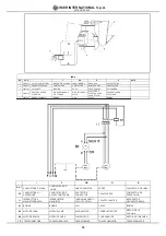
-  Switch  off  the  electric  motor  and  remove  the  plug  from  the
power  supply.
-  Unscrew  the  4  screws  that  secure  the  movable  belt  guard
(ref.  1).
- Loosen the 4 (ref. 2) screws that clamp the electric motor to
the blade support.
- Tension the belt using the nut (ref. 3): apply a force of about
F=6  Kg  to  the  centre  of  the  free  section  of  the  belt,  the  arrow
should be about f=6 mm (fig. 9).
- Tighten the screws on the electric motor, checking the alignment
of the motor pulley and the blade pulley
- Refit the guard and lock it using the 4 screws.

 - To avoid shortening the life of the belt, the bearings

and  the  blade  shaft,  do  not  overtension  the  belt.  Finally,
check  the  two  pulleys  are  aligned

17.7 DRIVE BELT REPLACEMENT

Repeat the operations described in section 17.6, replacing the
belt before tensioning it.

17.8  ENDOTHERMIC  ENGINE  MAINTENANCE

Refer  to  the  specific  instruction  manual  enclosed  with  the
endothermic engine for its correct routine maintenance.

17.9 REPAIRS


-  Do  not  start  the  saw  during  repair  work.

Only use genuine IMER spare parts and do not modify them.


-  If  the  guards  are  removed  to  carry  out  repairs,  they

must be refitted properly when the repair work is finished.

18.  TROUBLESHOOTING

  -  WARNING!  Before  carrying  out  any  maintenance

operations,  switch  off  the  machine,  and  remove  the  plug
from  the  power  socket

FAULT

CAUSE

REMEDY

Motor does not start
when switch is
turned

- Defective power
cable
- Plug not inserted in
socket correctly
- Power cable from

plug to control panel

detached
- Loose wire inside
motor circuit board
- A wire has become
disconnected inside
the panel
- Faulty main switch
-The overload safety
device has been
activated.

- Check power cables

- Ensure correct
connection
- Connect cable- re

-Connect wire

- Remake the
connection

- Replace switch

-Wait for a few minutes
and then try restarting
the machine.

Horizontal carriage
movement not
smooth

- Guide rails dirty

- Clean the guide rails

Lack of cooling water
supply to blade

Refer to section 17.5: "cleaning and
maintenance of cooling circuit" (Chapter 17.5)

Blade does not cut

- Blade is worn

- Drive belt not
tensioned

- Fit new blade

-Tension the belt

Motor starts but
blade does not rotate

Belt is broken

Replace drive belt

Summary of Contents for 1188800

Page 1: ...ONRY 500 1188800 1188802 3210575 R01 2010 01 I SEGATRICE Manuale di uso manutenzione e ricambi F SCIE Manuel utilisation entretien pieces de rechange GB SAWING MACHINE Operating maintenance spare part...

Page 2: ...me 11 Manivelle de r glage 12 Pi ce couper 13 Lame 14 Ch ssis 15 Vis de terre 16 P dale 17 Boulon de but e t te 18 Protection lame GB 1 Carriage locking lever 2 Spray guard 3 Electric motor 4 Blade su...

Page 3: ...lla 2 sono riportati i livelli d immissione sonora ambientale misurato sulla segatrice Lwa secondo EN ISO 3744 ed il livello di pressione sonora misurato all orecchio dell operatore a vuoto LPA TABELL...

Page 4: ...pestivo al ritorno della tensione dopo un interruzione dovuta a mancanza di energia elettrica Per riprendere il lavo ro al ritorno della tensione premere il pulsante nero sul magnetotermico rif 7 fig...

Page 5: ...ppo e sfilare la vasca lateralmen te dal lato destro o sinistro 17 3 PULIZIA PIANI DI RIFERIMENTO Ipianidiappoggiodevonoesseremantenutipuliti Depositidisporcosu dette superfici possono determinare imp...

Page 6: ...nue ou segments toujours r frig r es par eau peuvent tre utilis es Il est absolument interdit d utiliser des lames pour la coupe sec et de couper d autres mat riaux non pr vus dans cette sp cification...

Page 7: ...e le courant est r tabli apr s une interruption due une ventuelle coupure Pour reprendre le travail dans ce cas presser le poussoir noir sur le magn tothermique r f 7 fig 1 F F 14 MONTAGE DE LA LAME F...

Page 8: ...ans d appui doivent tre toujours tr s propres La crasse sur ces plans peut compromettre la pr cision de la coupe 17 4NETTOYAGE DES GLISSIERES Enlever toute la crasse qui pourrait se former sur les gli...

Page 9: ...amage caused by improper use of the above machine 5 CUTTING CAPACITY max cutting capacitywith vertical blade 205mm in one single pass max height of workpiece 420 mm min width of workpiece 50mm max cut...

Page 10: ...to that indicated on the blade guard Centre the blade against the fixed flange position the mobile flange and tighten the blade locknut fully down by rotating anticlockwise left thread Refit the movi...

Page 11: ...ut fig 10 WARNING Before starting the panel saw for the first time or when starting it after long periods of inactivity fill the pump with water as described above At the end of every shift unscrew th...

Page 12: ...d hnlichem konzipiert Dazu d rfen lediglich st ndig mit Wasser gek hlte Diamanttrennscheiben mit geschlossenem Rand oder Segmenten eingesetzt werden Es d rfen auf keinen Fall Trocken Trennscheiben ver...

Page 13: ...r cken 14 MONTAGE DER TRENNSCHEIBE Abb 5 Die funf Befestigungsschrauben des beweglichen Scheibenschutzes Bez 3 mit einem Inbusschl ssel Nr 10 abdrehen Die Befestigungsmutter durch Drehen im Uhrzeigers...

Page 14: ...17 1 REINIGUNG DES WASSERBECKENS Den Verschluss abnehmen und das Becken entleeren Abgelagerte Bearbeitungsr ckst nde mit einem Wasserstrahl aussp len 17 2 AUSBAU DES BECKENS Bez Abb 7 Die Wanne wird e...

Page 15: ...sectores con interrupciones delgadas siempre refrigerados por agua No se deben usar en absoluto hojas para cortar en seco y no se deben cortar otros materiales no previstos en esta especificaci n IMER...

Page 16: ...ot rmico ref 7 fig 1 El motor est protegido contra la reactivaci n intem pestiva al restablecerse la tensi n despu s de una interrupci n debida a la falta de energ a el ctrica Para reanudar el trabajo...

Page 17: ...pueden provocar imprecisiones de corte 17 4 LIMPIEZA DE LAS GU AS DE DESLIZAMIENTO Conviene mantener las gu as limpias removiendo toda traza de suciedad all acumulada 17 5 LIMPIEZA Y MANTENIMIENTO DE...

Page 18: ...4 Fig 5 Fig 7 Fig 8 Masonry 500 Tab 3 Lunghezza cavo m Longueur c ble m Cable length m Kabel L nge m Longitud cable m V 380 I 9 6 A 0 18 19 29 30 48 V 415 I 8 8 A 0 20 21 33 34 51 sezione cavo mm sec...

Page 19: ...Type of machine 2 Part number and position number of each part 3 Serial number and year of manufacture reported on the machine s identification plate SYMBOL Interchangeability example Pos 1 P n 32045...

Page 20: ...SHEIBE ARANDELA 13 2265675 PARACOLPO PARE COUPS SHOCK ABSORBER STO F NGER PARACHOQUES 14 3210342 TUBO PEDALE TUBE P DALE PEDAL PIPE ROHR PEDAL TUBO DEL PEDAL 15 3210569 GRUPPO TESTA DI TAGLIO GROUPE T...

Page 21: ...ASSERD SE TUBO AGUA 56 3210629 CUSCINETTO PALIER BEARING LAGER COJINETE 6006 2RS 57 2218075 RUBINETTO ROBINET VALVE HAHN GRIFO 58 3210322 CARTER LAMA CARTER LAME BLADE COVER SCHEIBENGEH USE C RTER HOJ...

Page 22: ...A D O R 7 3 2 0 3 9 2 1 V ITE V IS B O LT S C H R A U B E TO R N IL L O M 5 X 1 0 Z 8 3 2 1 0 5 7 3 P U L E G G IA P O U L IE P U L L E Y R IE M E N S C H E IB E P O L E A 9 1 2 2 2 0 5 9 V ITE V IS B...

Page 23: ...INA DI MINIMA BOBINE COIL SPULE BOBINA I F GB D E R S T CONDUTTORE DI LINEA CONDUCTEUR DE LIGNE LINE CONDUCTOR LEITER CONDUCTOR DE LINEA PE CONDUTTORE DI PROTEZIONE CONDUCTEUR DE PROTECTION TERRE PROT...

Page 24: ......

Page 25: ...D INSTALLATION PLACE OF INSTALLATION INSTALLATIONSORT LUGAR DE INSTALACI N VERIFICA PARTI DELLA MACCHINA ESSAIS PARTIES DE LA MACHINE MACHINE PART TESTS ABNAHME DER MASCHINENKOM PONENTEN PRUEBA DEL P...

Page 26: ...D INSTALLATION PLACE OF INSTALLATION INSTALLATIONSORT LUGAR DE INSTALACI N VERIFICA PARTI DELLA MACCHINA ESSAIS PARTIES DE LA MACHINE MACHINE PART TESTS ABNAHME DER MASCHINENKOM PONENTEN PRUEBA DEL P...

Page 27: ...gen Bestimmungen der EG Richtlinie 2006 42 EG und 2000 14 EG mit dem entsprachenden Rechtserl zur Umsetzung der Richtline ins nationale Recht Corresponde a las exigencias b sicas de le directive 2006...

Page 28: ......

Page 29: ...rication tous les transferts vers et de notre centre assistance pour des r parations chez le client seront charg au client Les r parations en garantie m me s elles sont effectu es chez un des nos cent...

Page 30: ...Schmiermittel verursachten Sch den bei durch eine nicht sachgerechte Schaltanlage durch St rungen im Versorgungsnetz oder durch nicht den Anweisungen in den Gebrauchs und Wartungsanleitungen entsprech...

Page 31: ......

Reviews: