v
Changes in contact closure status are logged in the PDU event history log.
v
When temperature and humidity values exceed user-selectable limits, the event
is logged in the PDU event history log.
Installing the environmental monitoring probe
To install the environmental monitoring probe, complete the following steps:
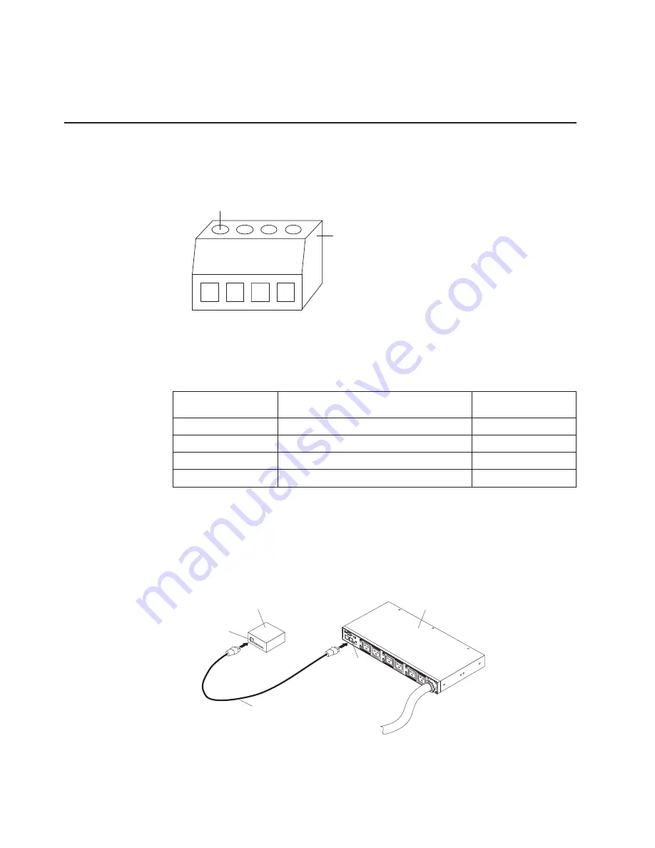
1. If applicable, connect external contact closure inputs to the screw terminals on
the environmental monitoring probe.
Environmental
monitoring probe
screw terminals
Pin 1
Note:
Contact closure device 1 is connected between pins 1 and 2. Device 2 is
connected between pins 3 and 4 (as labeled to show device 1 and 2). Contact
closure devices can be normally open or normally closed.
Table 3. Environmental monitoring probe screw terminal pin assignment
Pin number
Description
Normally open/
normally closed
1
Contact 1 return
Normally closed
2
Contact 1 signal input
Normally open
3
Contact 2 return
Normally closed
4
Contact 2 signal input
Normally open
2. Connect the CAT5 network cable that comes with the PDU to the environmental
monitoring probe RJ-45 connector and to the RJ-45 console connector on the
PDU.
Note:
If the cable is not long enough for your configuration, you can use a
cable that is 20 m (65.6 ft) or less.
LA
N
Ethernet cable
RJ-45
console
connector
RJ-45
connector
PDU
Environmental
monitoring
probe
1
2
3
4
5
6
3. Make sure that the PDU has a network connection, the power cord is
connected, and the power to the PDU is turned on. The environmental
monitoring probe is automatically recognized by the PDU.
46
DPI C13 PDU+, DPI C13 3-phase PDU+, DPI C19 PDU+, and DPI C19 3-phase PDU+: Installation and Maintenance Guide


