background image

10

Ikusi Flow guide

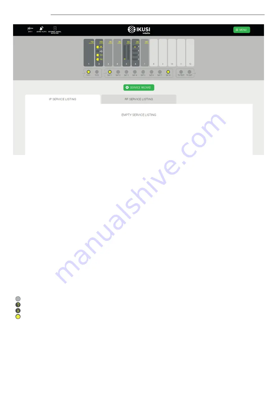
In the example, the top bar informs that two antennas have been connected: one terrestrial antenna identified as DTV1 and 
one satellite dish pointing to Astra 19.2°E satellite. Also, you could see that RF signal that has not been generated by Ikusi 
Flow has been detected.

In the same example, you can see that the headend consists of one FLOW PSU module, one FLOW HUB module, two FLOW IN 
modules, one FLOW SEC module with one FLOW CAM, one FLOW ENC module with one FLOW HDMI source connected to it, and 
one FLOW OUT module.

Also, you can see that there are three coaxial cables connected to the inputs. One of them with terrestrial signal and the other 
two with Astra 19.2°E satellite signal. Clicking in each of the used satellite connectors, you could see that the connected 
polarities are Astra 19.2°E Vertical Low and Astra 19.2°E Horizontal High.

In the required settings screen, the output type that has been selected is IP+RF. For that reason, there are two taps with the 
service list : one for IP and another one for RF. Both lists are empty, since the headend has not been configured yet.

3.4 Automatic scan & LNB powering

Ikusi Flow performs an automatic scanning of the signals. Scanning is launched automatically as soon as a coax cable is 
connected to the input connectors. During the scanning process, SCANNING message appears in the screen. Until scanning 
ends, you will not be able to add services through the Service wizard. The input signal connectors will inform about the status 
and the result of the scanning, using the following color code:

    No cable detected
    Detected cable, scanning
    Detected cable without signal
    Detected cable, ended scanning, detected services

Each connector automatically powers the preamplifiers connected to it (in the case of T/C connectors) with 12/24V 
(depending on country configuration) or the LNBs (in the case of SAT connectors) with 12V (required voltage to power a 
Quattro LNB).

Moreover, SAT1 and SAT2 connectors are able to manage universal LNBs (or dual or quad). If this is your case, before 
launching the Service wizard, modify the power configuration of those connectors. To do that, click over the connector. 
A window where you could configure the type of LNB will open.

Summary of Contents for Flow

Page 1: ...Headend Installation and Setting Ikusi Flow guide Ikusi Flow ...

Page 2: ...cabinet mounting 3 2 2 Wall mounting 5 2 3 Installation environment recommendations 6 3 BASIC CONFIGURATION 6 3 1 Connection to the headend 6 3 2 Initial configuration 7 3 3 Home screen 9 3 4 Automatic scan LNB powering 10 3 5 Service wizard 13 3 6 Home screen review 25 ...

Page 3: ...w After that it describes the steps that must be followed in order to define a channel line up while mainly focusing on the Service wizard 2 MOUNTING Ikusi Flow can be installed both in a rack cabinet and in wall Both types of installations are described below 2 1 Rack cabinet mounting When opening the box containing Ikusi Flow you will find a set of modules numbered from 1 to 5 Follow the order o...

Page 4: ...til the connectors reach the end After inserting it connect the power cord Step 3 Install FLOW HUB Extract FLOW HUB module from the box numbered as 3 The module must be inserted in the second slot of FLOW BASE Put it in the rails and slide it until the connectors reach the end In the case of IPTV installation connect TV1 and TV2 ports to two ports of the backbone Gigabit Ethernet switch ...

Page 5: ... deflector plate from the box numbered as 5 and insert it in FLOW BASE as it is shown in the picture The lower deflector plate will allow to gather the coaxial cables Repeat the same process with the upper deflector plate Finally put the cover If the cover is properly inserted the fans will start spinning 2 1 Wall mounting Step 1 Install FLOW BASE Extract FLOW BASE from the box numbered as 1 The f...

Page 6: ...this device is placed in a damp room The device should not be used in a very dusty or saline environment Dust or salt particles and other foreign objects may damage the device Do not expose the device to extreme vibrations It may damage the internal components 3 BASIC CONFIGURATION 3 1 Connection to the headend Ikusi Flow is configured through a web page generated by the own headend To access to t...

Page 7: ... time you access to the headend you must introduce a set of basic data Step 1 Language and password In this first screen you must choose the desired language for the user interface You must also define the password that will be used in the next connections ...

Page 8: ...t to the proposed one push button to edit them Type of output choose IP when the TV distribution network is pure IP RF when it is pure RF or IP RF when the distribution network is mixed Output modulation select the type of modulation used in the RF distribution TV type select the type of TVs that are being used in the installation HD or SD This parameter will be used by the headend in order to cho...

Page 9: ...guish this particular headend with respect to others 3 3 Home screen It is the main screen of the user interface It allows to Know which antennas are being used Know if the current RF distribution is conveyed any TV signal that has not been generated by Ikusi Flow Access to the advanced menu Review each of the modules and its status Launch the service wizard Know which channel line up is currently...

Page 10: ...for IP and another one for RF Both lists are empty since the headend has not been configured yet 3 4 Automatic scan LNB powering Ikusi Flow performs an automatic scanning of the signals Scanning is launched automatically as soon as a coax cable is connected to the input connectors During the scanning process SCANNING message appears in the screen Until scanning ends you will not be able to add ser...

Page 11: ...you use a 13 18V without tones switching LNB tipically used in Australia select TYPE OF LNB Quad Dual In LNB POLARITY select the desired polarity Horizontal or Vertical In the case you use a Universal LNB select TYPE OF LNB Universal ...

Page 12: ...12 Ikusi Flow guide In LNB POLARITY select the desired polarity Horizontal High Horizontal Low Vertical High or Vertical Low Once the connector setup has been done push SAVE button ...

Page 13: ...ARD button Step 1 Terrestrial services selection This screen allows the selection of the desired terrestrial services There are two identical tabs one for defining the terrestrial services that will be conveyed in the IP network IP TERRESTRIAL SERVICES and the other one for defining the terrestrial services that will conveyed in the RF network RF TERRESTRIAL SERVICES ...

Page 14: ...e grouped by mux To choose a com plete terrestrial mux push button Also you can select particular services clicking them individually Perform the same procedure in the RF tab with the services that must be conveyed in RF in the current example they are the same as in IP Push button to advance to the next step ...

Page 15: ...n of the desired satellite services As the previous step there are two identical tabs one for defining the satellite services that will be conveyed in the IP ne twork IP SAT SERVICES and the other one for defining the satellite services that will conveyed in the RF network RF SAT SERVICES ...

Page 16: ...u type FOX a list with all the detected services whose name include FOX will appear To obtain more information about a particular service click over the name of the service For example clicking over FOX LIFE HD service the following window will open To add the service to the output push ADD SERVICE button Also it can be added from the previous screen pushing ...

Page 17: ...t NOTE If instead of looking for a specific service you leave the search box empty and press the button a list will appear with all the services detected in the satellite cables Repeat the process in the RF tap to configure the satellite services that must be conveyed in the RF network ...

Page 18: ... allows the selection of the desired services comming from HDMI sources DVD STB There are two identical tabs one for defining the HDMI services that will be conveyed in the IP network IP HDMI SERVICES and the other one for defining the HDMI services that will conveyed in the RF network RF HDMI SERVICES ...

Page 19: ... A input of the FLOW ENC module inserted in the 6th slot By default the assigned name to the service is composed by the combination of the slot number and the connector position in this case 6 A If you want to change the name of the service push button and edit it in the example the name has been changed from 6 A to STB 1 Repeat the process in the RF tap to configure the HDMI services that must be...

Page 20: ...adio that shares mux with the already selected services in the pre vious steps but have not been added by the user Taking for granted that the IP network has enough bandwidth these services could be added to the IP channel line up without using any additional hardware IP SERVICES FOR FREE If it so wishes you can add any of these services in this screen ...

Page 21: ...There are two reasons why a channel could be declared as non eligible 1 The headend has detected another signal in the installation that is using that channel and therefore it could cause some interference Those channels are labelled with the icon You can relaunch the detection of external signals that has not been generated by Ikusi Flow pushing the SCAN button 2 The user has decided manually tha...

Page 22: ...en allows to perform the last adjustments over the channel line up before being sent to the headend There are two tabs one related with the services that will be conveyed in the IP network IP SERVICES LISTING and another one with the services that will conveyed in the RF network RF SERVICES LISTING ...

Page 23: ...elected a single multicast stream will be generated That stream will include all the languages of that multi language service IP you will be able to edit the IP address and port suggested automatically by the headend individually To do that click over button and configure the desired IP address and port SERVICE NAME TO SHOW you can change the service name that will be shown in the TV To do that ed...

Page 24: ...herefore the final user can select the desired language simply changing the channel When combined languages mode is selected a single service will all the languages will be generated LCN VCN you will be able to edit the LCN VCN value suggested automatically by the headend individually To do that click over button and configure the desired LCN VCN SERVICE NAME TO SHOW you can change the service nam...

Page 25: ...he following one In this screen you can see a list of the configured services in IP and in RF In the case any of them fails it become red Also from this screen you will be able to Change the RF output level To do that push TV OUT connector A window with a slider will open Move the slider to adjust the output level ...

Page 26: ... information about each module When you click over a module a window opens with information about position serial number hardware version firmware version temperature other data related to each particular module and data about the TV processing that it is performing From this window the module can be rebooted pushing REBOOT button ...

Page 27: ...27 Ikusi Flow guide ...

Page 28: ...Paseo Miramón 170 20014 San Sebastián Spain T 34 943 44 88 00 television ikusi com www ikusi tv ...

Reviews: