65
Fig. 2
Fig. 4
Fig. 1
Fig. 3
Fig. 5
A
B
B
F
F
B
G
B
D
E
C
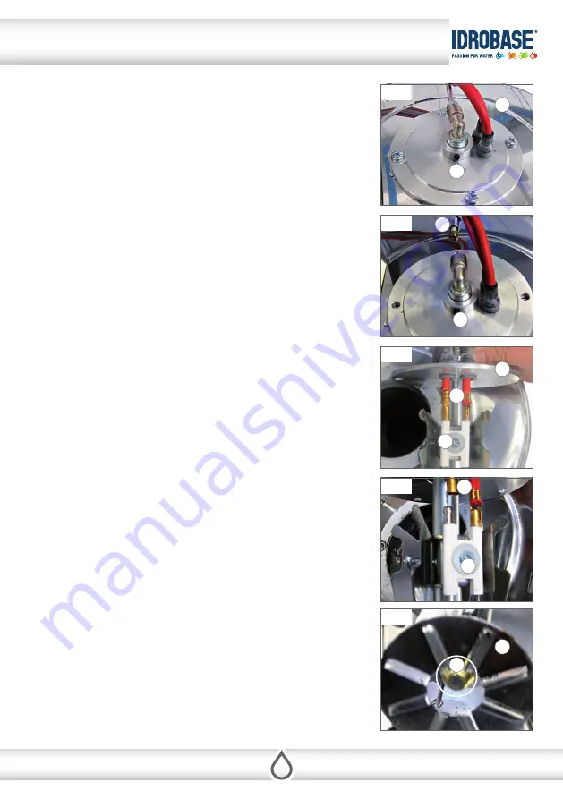
ELECTRODES AND FUEL NOZZLE MAINTENANCE
T2000/2 has been designed to enable thinking to the safety of operators and to let an
easy maintenance.
The combustion head is an example of it: it is realized to avoid the direct contact with
electrodes which are inside the heater. It make pratically impossible to touch elec-
trodes and clutches of high tension cables with hands or metal parts. All this is very
pratical in the maintenance, simply unscrewing and removing the complete combu-
stion head.
1. Fig. 1
showns the cover (
A
) of the heater in which is fixed the combustion head
(
B
). On the combustion head are located electrodes (
C
) and fuel nozzle (
D
).
2. Remove the fuel supply pipe (
E
) as show in
fig. 2
, and unscrew 4 fixing screws.
3. Remove the head combustion group (
fig. 3
).
4. To replace the electrodes (
C
) (
fig. 4
):
•
Remove the red high cable tension (
F
) that connects the ignition transformer
to the electrodes (
C
).
•
Remove the screw (
G
) that fixes the electrodes to the combustion head.
5. To clean the fuel filter nozzle (
D
) or to replace it (
fig. 5
):
•
Provide the key to remove the fuel nozzle (
D
) from the combustion head (
B
).
•
Remove the fuel nozzle and clean or replace the fuel filter or the complete fuel
nozzle..
9 - MAINTENANCE
Cop
yrigh
t ©2016 I
dr
obase G
roup
. A
ll righ
ts r
eser
ved
.


