


(C) IDM Energiesysteme GmbH
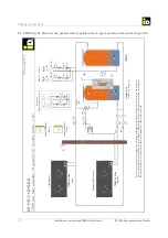
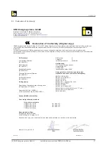
7. General description
Installation instructions TERRA AL 60 Max
36
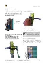
Heating connections
7. Start-up
7.1. Information regarding the start-up
Before starting up the TERRA heat pump ensure wa-
ter tightness on the heating side, rinse the heat pump
thoroughly,
fi
ll and ventilate the heat pump carefully.
Start-up requirements
- The heating and a possibly existing storage tank
have to be
fi
lled and ventilated.
- In the heat pump return, a
fi
lter ball valve is installed
in front of the condenser. After the system has been
fl
ushed for at least 30 minutes, the
fi
lter must be
cleaned (see chapter Hydraulic connection, section
Cleaning
fi
lter ball valve).
- At the start-up the complete heating bu
ff
er has to be
heated up to min. 20 °C. This can be performed e.g.
with the electric heating rod.
- The electrical installation must be completed and
fused properly.
- The heat pump may only be switched on if it is
properly
fi
lled on the coolant side as well as on the
heating side and if the electrical connections are in
place.
- At the start-up the maximum temperature limit has
to be set. The switch-o
ff
point at 62 °C must be
checked and, if applicable, the shut-down tempera-
ture then adapted.
- The heat pump is furnished with a delay time of 10
minutes, so that the compressor only starts after
this start-up delay.
- If the heat pump is to be drained on the heating
side in a frost-proof mode, the connection hose has
to be loosened at the heat pump return (plate heat
exchanger).
7.2. Switching the heat pump on for the very fi rst time
After pressing the main switch on the heat pump, the
start-up assistant is started after selecting the desired
language.
If an error occurs several times in sequence,
please contact your iDM customer service!
Customer service phone No.:____________________
In accordance with Regulation (EU)
No. 517/2014 of 01/01/2015 on certain
fl
uorinated greenhouse gases and in
accordance with Regulation (EU) No.
1516/2007, the operator of a heat pump
system is obligated to carry out regular
leak tests by a certi
fi
ed professional. The
interval may vary depending upon the
CO² equivalent capacity. The inspection
intervals are indicated in the Check- and
banking book.
7.4. Errors
The TERRA heat pump is furnished with a multitude
of safety switching device so that in the event of
disturbances no damage will take place to the equip-
ment.
If contrary to expectations the heat pump fails to func-
tion, please check the error message shown on the
display on the navigator regulation.
See the operating instructions of the navigator regu-
lation!
7.3. Operation
The TERRA heat pump is independently switched on
and o
ff
via the fully automatic navigator regulation.
See the separate operation and start-up instructions
for information on Operation and Start-up.
An annual inspection and maintenance of the system
by customer service is recommended, in particular
with regard to protecting the guarantee claims.


