


(C) IDM Energiesysteme GmbH
4. General description
Installation instructions TERRA AL 60 Max
13
In order to avoid damage, caused by ani-
mals such as rodents or insects, all cable
and pipe openings have to be closed.
4.
4.
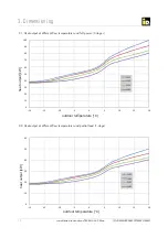
4. Dimensions
General des
General des
4. Placement and Installation
4.1. Installation instructions
The TERRA AL 60 Max is only designed for exterior
installation. Special actions has to be set for frost
protections.
Despite the possibility of speed reduction, the heat
pump should not be positioned adjacent to a living
room or bedroom. The relevant installation guide-
lines conforming to EN 378, for example, must be
observed.
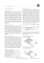
4.2. Customer preparation
Foundation:
The foundation should be level and stable. A base
can be provided by the customer or a paving slab can
be laid on a gravel base. The air source heat pump
should be positioned slightly higher than the immedi-
ate site pro
fi
le (minimum 200 mm).
If vibrations of the heat pump are transmitted via
fl
oors, ceilings, walls or other solids, this is referred to
as structure-borne noise.
To avoid this noise inside buildings or structure-borne
noise transmission, the heat pump has to be de-
coupled from the building. e.g. installation on a roof.
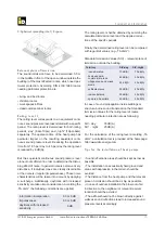
Space requirements:
The heat pump must be positioned so that there
is su
ffi
cient space for air intake and air outlet (see
minimum distances for exterior installation). It should
not be possible for the inlet and exhaust air openings
to become blocked by snow, leaves, etc. Installation
in wall niches is to be avoided.
Inlet air:
The inlet air must be free of impurities such as sand
and caustic materials such as ammonia, sulphur,
chlorine, etc.
4.3. Condensation run-o
ff
Air source heat pumps generate condensed water
when in operation. Per defrosting cycle, i.e. within 2
minutes up to 15 lt. of condensate can accumulate.
The condensation outlet should be conveyed into the
waste water channel by using the appropriate pipe
diameter for the machine.
The condensate must be able to run of also at tem-
peratures below 0 °C. The easiest way to guarantee
is by using the mounted heating cable, aktivated by
the Navigator control.
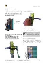
4.4. Heating connections
The heating connections must be installed with the
fl
exible hoses which are available as accessories.
These hoses are factory insulated.
In general, all lines outdoors should be kept as short
as possible. All pipes and wall openings must be pro-
fessionally heat-insulated and frost-protected during
installation.
4.5. Air outlet
On the air outlet exists an increased risk of frost. Rain
pipes, water-carrying pipes or water-carrying contain-
ers must not be located next to the outlet side.


