


(C) IDM Energiesysteme GmbH
6. General description
Installation instructions TERRA AL 60 Max
31
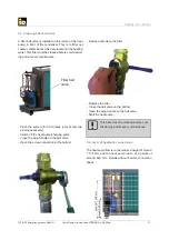
A network socket is already provided on the bottom surface of the cabinet. For plug and play
usage of myiDM (heat-pump control via internet). The network cable have to be plugged in there.
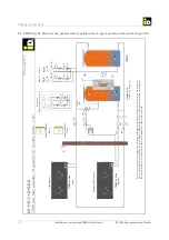
Data cable 2x2x0.5 mm²
Control current 3x1.5 mm²
Primary current compressor 5x16 mm²
P
y
p
Primary current heat pump (3+N 400V/50HZ)
Control current (1x230V/50HZ)
Sensor and control lines, on-
Network cable, on-site
If a heating element is used as a bivalence, the main power supply of the heating element is not
laid over the indoor unit, but is prepared by the customer on site.
6.
6.
6 Exterior installation
General description
General description
6. Electrical connection
6.1. Power supply
The electrical connection must be made by a quali
fi
ed person and must be registered with the local elec-
tricity company. The executive electrical company, is
responsible for the norm-compliant connection to the
electrical installation and the applied safety measure.
The mains voltage at the terminals of the heat pump
must be 400 V ± 10 %. The dimensions of the con-
necting cables must be checked by the executive
electric company.
A fault-current circuit breaker for the heat pump is not
required. The connection to the protective measure
„protective multiple earthing“ is su
ffi
cient. If never-
theless the protective measure „fault-current circuit
breakers,“ dispatched by the executive electric com-
pany, a separate fault-current circuit breaker for the
heat pump is recommended.
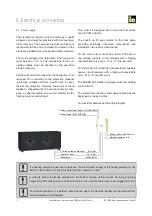
For data transmission, a shielded cable must be used. All electrical details can be derived from
the appropriate circuit diagram.
This must be designed as an all current sensitive
Type B (I
Δ
N
≥
30 mA).
The speci
fi
ed FI-types related to the heat pump
excluding externally connected components (see
Installation instructions, data sheets).
For the main current circuit as a result of the occur-
ring starting currents, circuit breakers with a tripping
characteristic curve Type „C“ or „K“ must be used.
For the control circuit and the optional electric auxiliary
heater, circuit breakers with a tripping characteristic
Type „B“ or „Z“ are su
ffi
cient.
The TERRA AL 60 Max is equipped with two starting
current limiter.
The electrical connection- and supply cables must be
designed as copper cables.
For electrical details see the wiring diagram.


