


(C) IDM Energiesysteme GmbH
6. General description
Installation instructions TERRA AL 60 Max
32
105
101
315
314
313
312
311
310
309
308
307
306
305
13
9
13
8
39
38
36
53
73
NN
34
32
N
33
31
N
30
29
28
N
26
27
25
N2
4
23
NN
22
N
N
21
20
EEV1 X2
EEV2 X4
95
94
93
92
91
90
89
88
87
86
85
84
83
82
81
80
79
78
77
76
75
74
73
72
71
70
69
68
67
66
65
64
63
62
61
60
59
58
57
56
55
54
53
52
51
50
43
42
41
40
+ H L
- SH
132 131 130
BE
CAN
LAN X33
RS232 X36
100
102
103 104
106
107 108
109
110
111 112
113 114 115 116 117 118 119 120 121
122 123
1
N
10
N
N1
1
N1
2
181
180
F4
F10
F9
F3
F7
F6
F1
F2
F5
X42
X2
X4
ON
2
1
ON
2
1
H4
H5
H6
H7
H3
H2
H1
S1
S2
X3
1
2
X6
X11
X8
X7
X5
K2
X10
X9
K3
K4
K1
79
H L
X1
Touchdisplay
X1
Ex
tension module internal I
/O
28
.0
D
IP-
Sw
itc
h
fo
r
R
S
-
Terminating resistor
D
IP-
Sw
itc
h
fo
r
C
AN
-
T
erminating resistor
Extension module
external /
Cascade participant
Extension module
internal
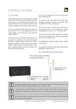
Electrical connections
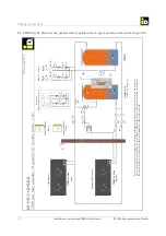
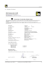
6.2. Connection diagram for the electric components
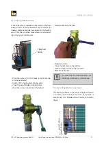
The central controller unit is located below the front
panel (below the operating unit). All connections on
the central unit are disconnectable.
Additional modules such as the internal extension
module for two further heating circuits, as well as the
extension module for three heating circuits and the
operating unit are connected as shown in the diagram
below.


