


(C) IDM Energiesysteme GmbH
Installation instructions TERRA AL 60 Max
35
M
ɾ
M
ɾ
M
ɾ
M
ɾ
72
73
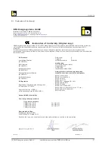
Room
thermostat
Zone valve with
end switch
Navigator
main board
Room 1
Room 2
Room 3
Zone 1
Zone 2
Zone 3
Room engine heating circuit A
Electrical connections
6.12. Maximum delimitation in underfl oor heating
In under
fl
oor heating circuits an additional application
thermostat has to be mounted and the appropriate
heating circuit feed has to be switched in series above
that.
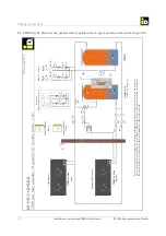
6.13. Sum signal zone valves
In setting the sum signal zone valve a requirement
is generated if one of the zone valves is open. The
di
ff
erence to the room thermostat function is that irre-
spective of heating or cooling operation a requirement
in the closed contact of a zone valve is generated.
If zone valves are used, a sum signal of
all zone valves can be generated to be
able to switch the heating and cooling
circuit ON resp. OFF with the thermostat
function.
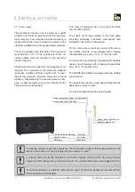
6.14. Connecting external specifi cations 0-10 V
To connect the reference value input 0-10 V, the in-
put of the air humidity sensor is used. Via this 0-10
V signal the regulation of the target temperature is
speci
fi
ed.
Information on the electric details are
found in the circuit diagram attached.
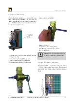
6.15. Opening and closing the electrical cabinet
To open the electrical cabinet, there is a recess with
a diameter of approx. 8mm on the underside of the
door. The locking mechanism is located about two
centimetres above the edge of the unit. Pressing the
locking bolt releases the lock. To lock the door again,
use a screwdriver or a pointed object into the recess
at the same time, the door can be closed completely.


