


(C) IDM Energiesysteme GmbH
5. General description
Installation instructions TERRA AL 60 Max
24
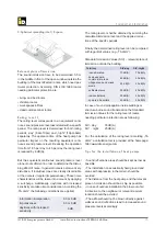
heat-pump
fl
ow
heat-pump
return
P
FIL
FIL
P
M73-2
M73-1 B14
TERRA AL
Buffer
heating water
brine
outdoor
intdoor
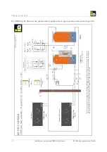
Basic scheme, only neccessary if an additional safety brine circuit is provided.
Heating connections
5.2. Frost protection
The hydraulic pipelines must be isolated expertly, and
they must be installed underneath the frost line.
For bivalent-alternative operating mode, or if longer
waiting periods could occur, in addition there is a frost
protection function for the outdoor unit. Falls the out-
door temperature below the antifreeze outside tem-
perature and the
fl
ow temperature of the heat pump
below the minimum temperature, the charge pump
starts, until the pipelines are again on temperature.
If the heat pump should be still equipped with an ad-
ditional intermediate brine circuit, it must be ensured
that the charging pump (M73-1) and the additional
onsite pump (M73-2) may use the same driven signal.
(safety-heat exchanger, brine-pump and accessories
have to be provided on site)
The charge pump and the on site pump can be con-
nected in parallel and driven via the signal of the
charge pump. The
fl
ow switch B14 must be installed
on the heating water side in a horizontal position.
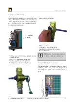
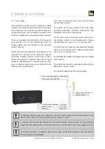
Flexible hoses
Two
fl
exible hoses (about 30 cm) are available as
accessories and are factory insulated. They have to
be mounted to the
fl
ow and the return of the heat-
pump.


