


FC6A S
ERIES
MICROS
MART
L
ADDER
P
ROGRAMMING
M
ANUAL
FC9Y-B1726
10-7
10: D
ATA
C
ONVERSION
I
NSTRUCTIONS
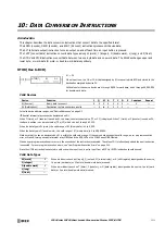
ATOH (ASCII to Hex)
Valid Devices
For valid device address ranges, see "Device Addresses" on page 2-1.
Special internal relays cannot be designated as D1.
When T (timer) or C (counter) is used as S2, the timer/counter current value (TC or CC) is displayed. When T (timer) or C (counter) is used as D1,
the data is written in as a preset value (TP or CP) which can be 0 through 65,535.
Valid values for source S1 data to convert are 30h to 39h and 41h to 46h. Make sure that the values for each source designated by S1 and the
quantity of digits designated by S2 are within the valid range. If the S1 or S2 data exceeds the valid range, a user program execution error will
result, turning on special internal relay M8004 and the ERR LED on the FC6A Series MICROSmart.
When a user program execution error occurs, the execution of the instruction is canceled. The value of D1 is left unchanged and the next instruction
is executed. For user program execution errors, see "User Program Execution Errors" on page 3-10.
Since the ATOH instruction is executed in each scan while input is on, a pulse input from a SOTU or SOTD instruction should be used.
Valid Data Types
S1, S1+1, S1+2, S1+3
→
D1
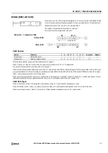
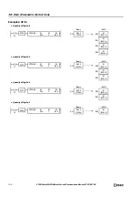
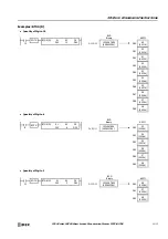
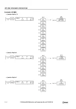
When input is on, the ASCII data, assigned by S1, is converted into 16-bit binary data.
The number of times is determined by the quantity of digits assigned by S2. The data
is then stored to the destination assigned by device D1.
Valid values for source data to convert are 30h to 39h and 41h to 46h.
The quantity of digits to convert can be 1 through 4.
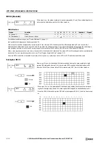
ATOH(W)
S1
*****
S2
*****
D1
*****
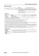
Device
Function
I
Q
M
R
T
C
D
P
Constant
Repeat
S1 (Source 1)
ASCII data to convert
—
—
—
—
—
—
X
—
—
—
S2 (Source 2)
Quantity of digits to convert
X
X
X
X
X
X
X
—
1-4
—
D1 (Destination 1)
Destination to store conversion results
—
X
X
X
X
X
—
—
—
W (word)
X
When a bit device such as I (input), Q (output), M (internal relay), or R (shift register) is assigned as the source
or destination, 16 points (word data) are used.
When a word device such as T (timer), C (counter), or D (data register) is assigned as the source or destination,
1 point (word data) is used.
I (integer)
—
D (double word)
—
L (long)
—
F (float)
—
Summary of Contents for MICROSmart FC6A Series
Page 1: ...B 1726 7 FC6A SERIES Ladder Programming Manual ...
Page 8: ...Preface 7 FC6A SERIES MICROSMART LADDER PROGRAMMING MANUAL FC9Y B1726 ...
Page 32: ...1 OPERATION BASICS 1 20 FC6A SERIES MICROSMART LADDER PROGRAMMING MANUAL FC9Y B1726 ...
Page 96: ...3 INSTRUCTIONS REFERENCE 3 18 FC6A SERIES MICROSMART LADDER PROGRAMMING MANUAL FC9Y B1726 ...
Page 130: ...4 BASIC INSTRUCTIONS 4 34 FC6A SERIES MICROSMART LADDER PROGRAMMING MANUAL FC9Y B1726 ...
Page 192: ...9 SHIFT ROTATE INSTRUCTIONS 9 12 FC6A SERIES MICROSMART LADDER PROGRAMMING MANUAL FC9Y B1726 ...
Page 272: ...12 DISPLAY INSTRUCTIONS 12 24 FC6A SERIES MICROSMART LADDER PROGRAMMING MANUAL FC9Y B1726 ...
Page 284: ...14 REFRESH INSTRUCTIONS 14 6 FC6A SERIES MICROSMART LADDER PROGRAMMING MANUAL FC9Y B1726 ...
Page 502: ...25 DATA LOG INSTRUCTIONS 25 22 FC6A SERIES MICROSMART LADDER PROGRAMMING MANUAL FC9Y B1726 ...
Page 546: ...26 SCRIPT 26 44 FC6A SERIES MICROSMART LADDER PROGRAMMING MANUAL FC9Y B1726 ...
Page 598: ...APPENDIX A 14 FC6A SERIES MICROSMART LADDER PROGRAMMING MANUAL FC9Y B1726 ...


