


FC6A S
ERIES
MICROS
MART
L
ADDER
P
ROGRAMMING
M
ANUAL
FC9Y-B1726
19-27
19: PID C
ONTROL
I
NSTRUCTION
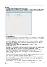
Settings
The
PIDD (PID with Derivative Decay)
dialog box contains the
Device
tab,
Controller
tab, and
Tuning
tab.
The devices used with the PIDD instruction are configured in the
Device
tab.
The initial values of the PIDD instruction parameters are configured in
Controller
and
Tuning
tabs.
■
Device tab
1. S1 (source 1): Control Register
Specify the first device of the data register range that stores the PIDD instruction control parameters.
Starting from the specified data register, 100 words of data registers are used. The devices that can be specified as data
registers are data registers D0000 to D7900 and D10000 to D61900.
When the PIDD instruction initialization input is turned on, the control registers are initialized with the values set on the
Controller
and
Tuning
tabs.
For the control registers, see "S1: Control Registers" on page 19-34.
2. S2 (source 2): Initialization Input
Specify the device that initializes the PIDD instruction control registers and control relays.
The device that can be specified as the initialization input is an external input or internal relay.
The parameters set on the
Controller
and
Tuning
tabs in the PIDD instruction dialog box are the initial values of the PIDD
instruction control registers and control relays. These initial values are downloaded to the PLC as the user program and stored in
the PLC's ROM. When the initialization input is turned on, the initial values of the PIDD instruction in ROM are stored in the
control registers and control relays.
When the initialization input is on, the initial values are stored with each scan. To only initialize the values one time, use the
initialization input in combination with the SOUT (single output up) instruction or the SOTD (single output down) instruction.
3. S3 (source 3): Control Relay
Specify the bit devices that will control PID control and store the status of PIDD instructions.
Starting from the specified internal relay, 32 internal relays are used. The devices that can be specified are internal relays M0 to
M7960 and M10000 to M21210. Special internal relays cannot be specified.
The role of each control relay bit is different. The operation of the PIDD instruction, such as direct control action/reverse control
action, derivative action enabled/disabled, self tuning enabled/disabled, and auto mode/manual mode/cascade control mode,
can be toggled by turning the corresponding bit on and off.
For the control relays, see "S3: Control Relay" on page 19-21.
4. PIDD No.
Assign a unique number from 0 to 31 to identify each PIDD instruction.
When performing the cascade control, specify the master PIDD instruction by its PIDD number.
1.
2.
3.
4.
Summary of Contents for MICROSmart FC6A Series
Page 1: ...B 1726 7 FC6A SERIES Ladder Programming Manual ...
Page 8: ...Preface 7 FC6A SERIES MICROSMART LADDER PROGRAMMING MANUAL FC9Y B1726 ...
Page 32: ...1 OPERATION BASICS 1 20 FC6A SERIES MICROSMART LADDER PROGRAMMING MANUAL FC9Y B1726 ...
Page 96: ...3 INSTRUCTIONS REFERENCE 3 18 FC6A SERIES MICROSMART LADDER PROGRAMMING MANUAL FC9Y B1726 ...
Page 130: ...4 BASIC INSTRUCTIONS 4 34 FC6A SERIES MICROSMART LADDER PROGRAMMING MANUAL FC9Y B1726 ...
Page 192: ...9 SHIFT ROTATE INSTRUCTIONS 9 12 FC6A SERIES MICROSMART LADDER PROGRAMMING MANUAL FC9Y B1726 ...
Page 272: ...12 DISPLAY INSTRUCTIONS 12 24 FC6A SERIES MICROSMART LADDER PROGRAMMING MANUAL FC9Y B1726 ...
Page 284: ...14 REFRESH INSTRUCTIONS 14 6 FC6A SERIES MICROSMART LADDER PROGRAMMING MANUAL FC9Y B1726 ...
Page 502: ...25 DATA LOG INSTRUCTIONS 25 22 FC6A SERIES MICROSMART LADDER PROGRAMMING MANUAL FC9Y B1726 ...
Page 546: ...26 SCRIPT 26 44 FC6A SERIES MICROSMART LADDER PROGRAMMING MANUAL FC9Y B1726 ...
Page 598: ...APPENDIX A 14 FC6A SERIES MICROSMART LADDER PROGRAMMING MANUAL FC9Y B1726 ...


