


4: B
ASIC
I
NSTRUCTIONS
4-20
FC6A S
ERIES
MICROS
MART
L
ADDER
P
ROGRAMMING
M
ANUAL
FC9Y-B1726
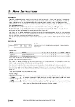
CC= and CC>= (Counter Comparison)
The CC= instruction is an equivalent comparison instruction for counter current values. This instruction will constantly compare
current values to the value that has been programmed in. When the counter value equals the given value, the desired output will
be initiated.
The CC>= instruction is an equal to or greater than comparison instruction for counter current values. This instruction will
constantly compare current values to the value that has been programmed in. When the counter value is equal to or greater than
the given value, the desired output will be initiated.
When a counter comparison instruction is programmed, two addresses are required. For a constant, specify the value in the range
of 0 to 65,535.
To indirectly specify the value, specify it with a data register number, and specify the value of the data register in the range of 0 to
65,535.
The preset value can be designated using a decimal constant or a data register. When a data register is used, the data of the data
register becomes the preset value.
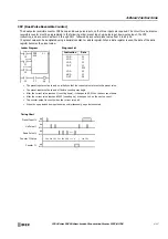
• The CC= and CC>= instructions can be used repeatedly for different preset values.
• The comparison instructions only compare the current value. The status of the counter does not affect this function.
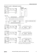
• The comparison instructions also serve as an implicit LOD instruction.
• The comparison instructions can be used with internal relays, which are ANDed or ORed at a separate program address.
• Like the LOD instruction, the comparison instructions can be followed by the AND and OR instructions.
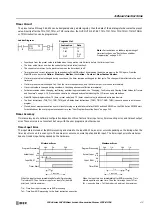
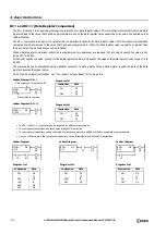
Ladder Diagram (CC=)
Ladder Diagram (CC>=)
Counter # to compare with
Preset value to compare
CC=
10
C2
CC>=
D15
C3
Q0
Q1
CC=
OUT
C2
10
Q0
Instruction
Data
CC>=
OUT
C3
D15
Q1
Instruction
Data
Program List
Program List
Ladder Diagram
Ladder Diagram
Ladder Diagram
I0
I0
M0
CC=
10
C5
CC=
10
C5
I0
CC=
10
C5
Q0
M0
Q0
Q0
CC=
OR
OUT
C5
10
I0
Q0
Instruction
Data
CC=
AND
OUT
C5
10
I0
Q0
Instruction
Data
CC=
OUT
LOD
AND
OUT
C5
10
M0
I0
M0
Q0
Instruction
Data
Program List
Program List
Program List
Summary of Contents for MICROSmart FC6A Series
Page 1: ...B 1726 7 FC6A SERIES Ladder Programming Manual ...
Page 8: ...Preface 7 FC6A SERIES MICROSMART LADDER PROGRAMMING MANUAL FC9Y B1726 ...
Page 32: ...1 OPERATION BASICS 1 20 FC6A SERIES MICROSMART LADDER PROGRAMMING MANUAL FC9Y B1726 ...
Page 96: ...3 INSTRUCTIONS REFERENCE 3 18 FC6A SERIES MICROSMART LADDER PROGRAMMING MANUAL FC9Y B1726 ...
Page 130: ...4 BASIC INSTRUCTIONS 4 34 FC6A SERIES MICROSMART LADDER PROGRAMMING MANUAL FC9Y B1726 ...
Page 192: ...9 SHIFT ROTATE INSTRUCTIONS 9 12 FC6A SERIES MICROSMART LADDER PROGRAMMING MANUAL FC9Y B1726 ...
Page 272: ...12 DISPLAY INSTRUCTIONS 12 24 FC6A SERIES MICROSMART LADDER PROGRAMMING MANUAL FC9Y B1726 ...
Page 284: ...14 REFRESH INSTRUCTIONS 14 6 FC6A SERIES MICROSMART LADDER PROGRAMMING MANUAL FC9Y B1726 ...
Page 502: ...25 DATA LOG INSTRUCTIONS 25 22 FC6A SERIES MICROSMART LADDER PROGRAMMING MANUAL FC9Y B1726 ...
Page 546: ...26 SCRIPT 26 44 FC6A SERIES MICROSMART LADDER PROGRAMMING MANUAL FC9Y B1726 ...
Page 598: ...APPENDIX A 14 FC6A SERIES MICROSMART LADDER PROGRAMMING MANUAL FC9Y B1726 ...


