


FC6A S
ERIES
MICROS
MART
L
ADDER
P
ROGRAMMING
M
ANUAL
FC9Y-B1726
27-5
27: F
LOW
C
ALCULATION
I
NSTRUCTIONS
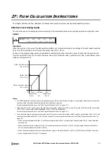
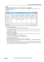
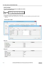
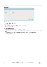
Settings
The
SCALE (Scale Analog Value)
dialog box contains the
Devices
tab and the
Settings
tab.
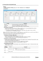
The
Devices
tab configures the devices used with the SCALE instruction. The
Settings
tab configures the initial values of the
SCALE instruction parameters.
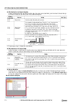
■
Devices tab
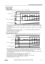
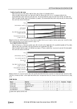
(1) S1 (Source 1): Input Value
Specify the data register as the device that stores the input value to convert.
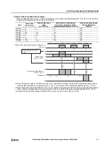
If the input value is greater than the input maximum value (S2+0) (input value > input maximum value (S2+0)), the input
maximum value (S2+0) is scaled.
If the input value is less than the input minimum value (S2+1) (input minimum value (S2+1) > input value), the input
minimum value (S2+1) is scaled.
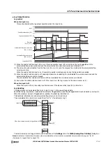
(2) S2 (Source 2): Control Register
Specify the data register that stores the input maximum value, input minimum value, output maximum value, output
minimum value, and the dead band.
8 continuous words are used starting from the specified data register.
For details on the control registers, see "S2: Control registers" on page 27-7.
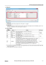
(3) S3 (Source 3): Initialization Input
Specify the input or internal relay as the device to initialize the control registers.
When the initialization input is on, the initial values configured on the
Settings
tab in the
SCALE (Scale Analog Value)
dialog box are stored in the control registers.
When the initialization input is on, the initial values are stored in the data registers with each scan. To execute initialization
only once, add the SOTU instruction (single output up) or the SOTD (single output down) instruction to the input conditions.
For how to configure the initial values, see "(2) Initial Value" on page 27-7.
(1)
(2)
(3)
(4)
(5)
(6)
Summary of Contents for MICROSmart FC6A Series
Page 1: ...B 1726 7 FC6A SERIES Ladder Programming Manual ...
Page 8: ...Preface 7 FC6A SERIES MICROSMART LADDER PROGRAMMING MANUAL FC9Y B1726 ...
Page 32: ...1 OPERATION BASICS 1 20 FC6A SERIES MICROSMART LADDER PROGRAMMING MANUAL FC9Y B1726 ...
Page 96: ...3 INSTRUCTIONS REFERENCE 3 18 FC6A SERIES MICROSMART LADDER PROGRAMMING MANUAL FC9Y B1726 ...
Page 130: ...4 BASIC INSTRUCTIONS 4 34 FC6A SERIES MICROSMART LADDER PROGRAMMING MANUAL FC9Y B1726 ...
Page 192: ...9 SHIFT ROTATE INSTRUCTIONS 9 12 FC6A SERIES MICROSMART LADDER PROGRAMMING MANUAL FC9Y B1726 ...
Page 272: ...12 DISPLAY INSTRUCTIONS 12 24 FC6A SERIES MICROSMART LADDER PROGRAMMING MANUAL FC9Y B1726 ...
Page 284: ...14 REFRESH INSTRUCTIONS 14 6 FC6A SERIES MICROSMART LADDER PROGRAMMING MANUAL FC9Y B1726 ...
Page 502: ...25 DATA LOG INSTRUCTIONS 25 22 FC6A SERIES MICROSMART LADDER PROGRAMMING MANUAL FC9Y B1726 ...
Page 546: ...26 SCRIPT 26 44 FC6A SERIES MICROSMART LADDER PROGRAMMING MANUAL FC9Y B1726 ...
Page 598: ...APPENDIX A 14 FC6A SERIES MICROSMART LADDER PROGRAMMING MANUAL FC9Y B1726 ...


