


FC6A S
ERIES
MICROS
MART
L
ADDER
P
ROGRAMMING
M
ANUAL
FC9Y-B1726
9-7
9: S
HIFT
/ R
OTATE
I
NSTRUCTIONS
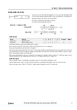
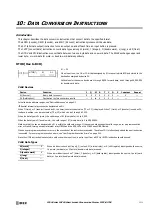
WSFT (Word Shift)
Valid Devices
For valid device address ranges, see "Device Addresses" on page 2-1.
When T (timer) or C (counter) is used as S1 or S2, the timer/counter current value (TC or CC) is displayed.
Valid Data Types
When a bit device such as I (input), Q (output), M (internal relay), or R (shift register) is assigned as source S1 or S2, 16 points are used.
When a word device such as T (timer), C (counter), or D (data register) is assigned as source S1 or S2, 1 point is used.
Special Internal Relay M8024: BMOV/WSFT Executing Flag
While the BMOV or WSFT is executed, M8024 turns on. When completed, M8024 turns off. If the CPU is powered down while
executing BMOV or WSFT, M8024 remains on when the CPU is powered up again.
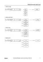
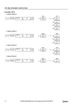
Example: WSFT
When input is on, N blocks of 16-bit word data, starting with device assigned by D1,
are shifted up to the next 16-bit positions. At the same time, the data assigned by
device S1 is moved to the device assigned by D1. S2 specifies the quantity of blocks to
move.
WSFT
S1
*****
D1
*****
S2
*****
When S2 = 3 (quantity of blocks to shift)
First 16-bit data
D1+0
Second 16-bit data
D1+1
Third 16-bit data
D1+2
Fifth 16-bit data
D1+4
Fourth 16-bit data
D1+3
S1 data
D1+0
First 16-bit data
D1+1
Second 16-bit data
D1+2
Fifth 16-bit data
D1+4
Third 16-bit data
D1+3
3 blocks (S2)
16-bit data
S1
16-bit data
S1
Device
Function
I
Q
M
R
T
C
D
P
Constant
Repeat
S1 (Source 1)
Source data for word shift
X
X
X
X
X
X
X
—
X
—
S2 (Source 2)
Quantity of blocks to shift
X
X
X
X
X
X
X
—
X
—
D1 (Destination 1)
First device address to shift
—
—
—
—
—
—
X
—
—
—
D100 through D102
→
D101 through D103
D10
→
D100
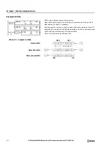
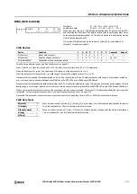
When input I0 is turned on, data of 3 data registers, starting with D100 assigned by
destination device D1, is shifted to the next data registers. Data of data register D10,
assigned by source device S1, is moved to D100 assigned by destination device D1.
SOTU
I0
S1
D10
D1
D100
WSFT
S2
3
2222
D101
1111
D100
3333
D102
4444
D103
5555
D104
1111
D101
12345
D100
2222
D102
3333
D103
5555
D104
12345
D10
12345
D10
Before shift:
After first shift:
Summary of Contents for MICROSmart FC6A Series
Page 1: ...B 1726 7 FC6A SERIES Ladder Programming Manual ...
Page 8: ...Preface 7 FC6A SERIES MICROSMART LADDER PROGRAMMING MANUAL FC9Y B1726 ...
Page 32: ...1 OPERATION BASICS 1 20 FC6A SERIES MICROSMART LADDER PROGRAMMING MANUAL FC9Y B1726 ...
Page 96: ...3 INSTRUCTIONS REFERENCE 3 18 FC6A SERIES MICROSMART LADDER PROGRAMMING MANUAL FC9Y B1726 ...
Page 130: ...4 BASIC INSTRUCTIONS 4 34 FC6A SERIES MICROSMART LADDER PROGRAMMING MANUAL FC9Y B1726 ...
Page 192: ...9 SHIFT ROTATE INSTRUCTIONS 9 12 FC6A SERIES MICROSMART LADDER PROGRAMMING MANUAL FC9Y B1726 ...
Page 272: ...12 DISPLAY INSTRUCTIONS 12 24 FC6A SERIES MICROSMART LADDER PROGRAMMING MANUAL FC9Y B1726 ...
Page 284: ...14 REFRESH INSTRUCTIONS 14 6 FC6A SERIES MICROSMART LADDER PROGRAMMING MANUAL FC9Y B1726 ...
Page 502: ...25 DATA LOG INSTRUCTIONS 25 22 FC6A SERIES MICROSMART LADDER PROGRAMMING MANUAL FC9Y B1726 ...
Page 546: ...26 SCRIPT 26 44 FC6A SERIES MICROSMART LADDER PROGRAMMING MANUAL FC9Y B1726 ...
Page 598: ...APPENDIX A 14 FC6A SERIES MICROSMART LADDER PROGRAMMING MANUAL FC9Y B1726 ...


