


FC6A S
ERIES
MICROS
MART
L
ADDER
P
ROGRAMMING
M
ANUAL
FC9Y-B1726
9-5
9: S
HIFT
/ R
OTATE
I
NSTRUCTIONS
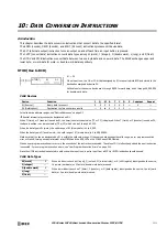
BCDLS (BCD Left Shift)
Valid Devices
For valid device address ranges, see "Device Addresses" on page 2-1.
When T (timer) or C (counter) is used as S2, the timer/counter current value (TC or CC) is displayed.
The number of digits that can be shifted as S2 are 1 through 7.
Make sure that the source data determined by S1 and S1+1 is between 0 and 9,999 for each data register. If either source data is over 9,999, a user
program execution error will result, turning on special internal relay M8004 and the ERR LED on the FC6A Series MICROSmart. When S2 is higher
than 7, a user program execution error will also result.
When a user program execution error occurs, the execution of the instruction is canceled. The data in S1 and S1+1 is left unchanged and the next
instruction is executed. For user program execution errors, see "User Program Execution Errors" on page 3-10.
Valid Data Types
When a word device such as D (data register) is assigned as source S1, 2 points (double-word data) are used.
When a bit device such as I (input), Q (output), M (internal relay), or R (shift register) is assigned as source S2, 16 points are used.
When a word device such as T (timer), C (counter), or D (data register) is assigned as source S2, 1 point is used.
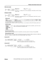
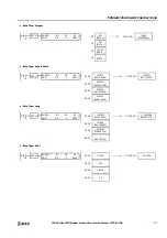
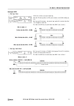
When input is on, the 32-bit binary data assigned by S1 is converted into 8 BCD digits, shifted
to the left by the quantity of digits assigned by S2, and converted back to 32-bit binary data.
Valid values for each of S1 and S1+1 are 0 through 9,999.
The number of digits that can be shifted is 1 through 7.
Zero is set to the lowest digit after each shift.
BCDLS
S1
*****
S2
*
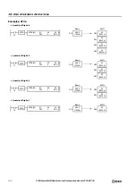
Before shift:
After shift:
0
2 3
1
MSD
S1
S1+1
Shift to the left
LSD
4
6 7
5
0
1
3 4
2
5
7 0
6
0
When S2 = 1 (digits to shift)
0
Device
Function
I
Q
M
R
T
C
D
P
Constant
Repeat
S1 (Source 1)
Data for BCD shift
—
—
—
—
—
—
X
—
—
—
S2 (Source 2)
Quantity of digits to shift
X
X
X
X
X
X
X
—
1-7
—
Summary of Contents for MICROSmart FC6A Series
Page 1: ...B 1726 7 FC6A SERIES Ladder Programming Manual ...
Page 8: ...Preface 7 FC6A SERIES MICROSMART LADDER PROGRAMMING MANUAL FC9Y B1726 ...
Page 32: ...1 OPERATION BASICS 1 20 FC6A SERIES MICROSMART LADDER PROGRAMMING MANUAL FC9Y B1726 ...
Page 96: ...3 INSTRUCTIONS REFERENCE 3 18 FC6A SERIES MICROSMART LADDER PROGRAMMING MANUAL FC9Y B1726 ...
Page 130: ...4 BASIC INSTRUCTIONS 4 34 FC6A SERIES MICROSMART LADDER PROGRAMMING MANUAL FC9Y B1726 ...
Page 192: ...9 SHIFT ROTATE INSTRUCTIONS 9 12 FC6A SERIES MICROSMART LADDER PROGRAMMING MANUAL FC9Y B1726 ...
Page 272: ...12 DISPLAY INSTRUCTIONS 12 24 FC6A SERIES MICROSMART LADDER PROGRAMMING MANUAL FC9Y B1726 ...
Page 284: ...14 REFRESH INSTRUCTIONS 14 6 FC6A SERIES MICROSMART LADDER PROGRAMMING MANUAL FC9Y B1726 ...
Page 502: ...25 DATA LOG INSTRUCTIONS 25 22 FC6A SERIES MICROSMART LADDER PROGRAMMING MANUAL FC9Y B1726 ...
Page 546: ...26 SCRIPT 26 44 FC6A SERIES MICROSMART LADDER PROGRAMMING MANUAL FC9Y B1726 ...
Page 598: ...APPENDIX A 14 FC6A SERIES MICROSMART LADDER PROGRAMMING MANUAL FC9Y B1726 ...


