


FC6A S
ERIES
MICROS
MART
L
ADDER
P
ROGRAMMING
M
ANUAL
FC9Y-B1726
18-69
18: P
ULSE
O
UTPUT
I
NSTRUCTIONS
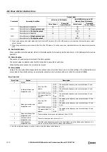
Settings
■
Devices tab
1. Select instruction
This item selects which ABS instruction to use ("ABS1", "ABS2", "ABS3", or "ABS4").
The absolute position counter to be initialized differs with the instruction.
The initialized status of D8240 to D8247 can be checked with the absolute position counter initialized flags defined in D8239
(absolute position control status).
When the FC6A Series MICROSmart switches from stop to run, 0 (not initialized) is stored in the absolute position counter
initialized flags. Then when the absolute position counters are initialized using the ABS instruction, 1 (initialized) is stored.
Command
Absolute Position Counter
Special Data
Register
Description
Instructions that Update the Absolute
Position Counter
ABS1
Absolute Position Counter 1
High word D8240
-2147483648
to
2147483647
ABS1/RAMP1
/ARAMP1/ZRN1/JOG1
Low word D8241
ABS2
Absolute Position Counter 2
High word D8242
ABS2/RAMP2
/ARAMP2/ZRN2/JOG2
Low word D8243
ABS3
Absolute Position Counter 3
High word D8244
ABS3/RAMP3
/ARAMP3/ZRN3/JOG3
Low word D8245
ABS4
Absolute Position Counter 4
High word D8246
ABS4/RAMP4
/ARAMP4/ZRN4/JOG4
Low word D8247
*1 The upper and lower data registers change according to the 32-bit data storage method specified. For details, see "32-bit Data Storage" on
*2 The values of the absolute position counters are retained by the backup battery even when the power is turned off. When a keep data error
occurs, the values are initialized to 0.
*3 The special data registers are read only. To change the values of D8240 to D8247, use the ABS instruction.
*4 When the RAMP, ARAMP, ZRN, and JOG instructions are used with Reversible control disabled, the absolute position counters are not
updated.
*5 When specify absolute position mode is enabled in the RAMP instruction, the target position is specified as the absolute position. When using
specify absolute position mode in the RAMP instruction, initialize the corresponding absolute position counter in advance with the ABS
instruction. For details, see "RAMP (Trapezoidal Control)" on page 18-15.
Device Number
Parameter Name
Bit Position
Description
D8239
Absolute Position Control Status
bit0: Absolute Position Counter 1 Initialized Flag
0: Not initialized
1: Initialized
bit1: Absolute Position Counter 2 Initialized Flag
bit2: Absolute Position Counter 3 Initialized Flag
bit3: Absolute Position Counter 4 Initialized Flag
bit4 to bit15
Reserved
1.
2.
Summary of Contents for MICROSmart FC6A Series
Page 1: ...B 1726 7 FC6A SERIES Ladder Programming Manual ...
Page 8: ...Preface 7 FC6A SERIES MICROSMART LADDER PROGRAMMING MANUAL FC9Y B1726 ...
Page 32: ...1 OPERATION BASICS 1 20 FC6A SERIES MICROSMART LADDER PROGRAMMING MANUAL FC9Y B1726 ...
Page 96: ...3 INSTRUCTIONS REFERENCE 3 18 FC6A SERIES MICROSMART LADDER PROGRAMMING MANUAL FC9Y B1726 ...
Page 130: ...4 BASIC INSTRUCTIONS 4 34 FC6A SERIES MICROSMART LADDER PROGRAMMING MANUAL FC9Y B1726 ...
Page 192: ...9 SHIFT ROTATE INSTRUCTIONS 9 12 FC6A SERIES MICROSMART LADDER PROGRAMMING MANUAL FC9Y B1726 ...
Page 272: ...12 DISPLAY INSTRUCTIONS 12 24 FC6A SERIES MICROSMART LADDER PROGRAMMING MANUAL FC9Y B1726 ...
Page 284: ...14 REFRESH INSTRUCTIONS 14 6 FC6A SERIES MICROSMART LADDER PROGRAMMING MANUAL FC9Y B1726 ...
Page 502: ...25 DATA LOG INSTRUCTIONS 25 22 FC6A SERIES MICROSMART LADDER PROGRAMMING MANUAL FC9Y B1726 ...
Page 546: ...26 SCRIPT 26 44 FC6A SERIES MICROSMART LADDER PROGRAMMING MANUAL FC9Y B1726 ...
Page 598: ...APPENDIX A 14 FC6A SERIES MICROSMART LADDER PROGRAMMING MANUAL FC9Y B1726 ...


