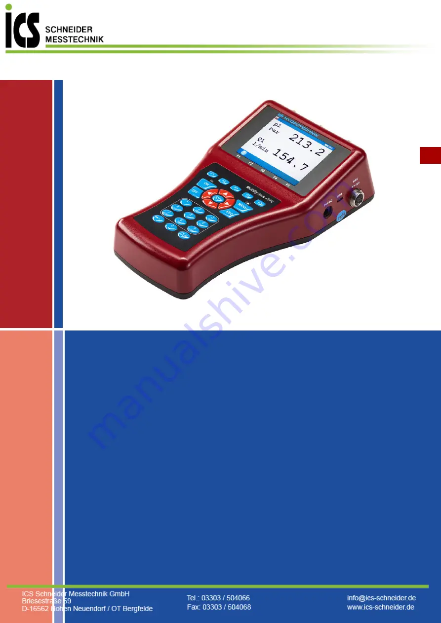
MultiSystem 4070
Universal Portable Measuring System
Firmware Version 1.2
Handbook Version 1.2
ENG
Operating Instructions
Page 1: ...MultiSystem 4070 Universal Portable Measuring System Firmware Version 1 2 Handbook Version 1 2 ENG Operating Instructions ENG ...
Page 2: ...ment On and Off 22 Operation of the instrument software 23 Navigating in the instrument software 24 Favorites 25 User defined softkeys 26 Softkeys Symbols text 26 Select operating language 27 Adjust number format 28 Set date and time 29 Connect sensors 29 Enter sensor parameters 30 Record measuring data 32 Delete measuring data 33 Display information on selected file 34 Connect a PC and transfer d...
Page 3: ...struments 123 Connecting a measuring instrument electrically 123 Serial coupling 124 Parallel coupling 125 Use of the MultiXtend Trigger 125 Program instruments 126 Program the Master instrument 126 Program Slave instruments 126 Start recording 126 Transfer and evaluate measured values 127 Connecting MultiXtend A and T 127 Enable CAN bus 128 Program CAN channels 129 Activate MultiXtend power suppl...
Page 4: ...t measurements Handling information for the MultiSystem 4070 Never expose the instrument to excessive heat or moisture and observe the technical data Do not store the instrument in humid or dusty locations or at temperatures below freezing point Never submerge the instrument into water or other liquids Never let liq uids come into the instrument Never open the instrument Do not use the instrument ...
Page 5: ... are reconnected the measuring instrument must be switched off and on again to allow the sensor data to be adopted Information about handling batteries Always keep batteries away from heat sources and open fire Never submerge batteries into water Never disassemble repair or modify the batteries Never short circuit the contacts of batteries Use only batteries that are installed or delivered by HYDR...
Page 6: ...All rights reserved to this manual this includes the reproduction and or duplication in any conceivable form e g by photocopying printing on any data recording media or in translated form Reproduction of this manual is only permitted with a written approval of HYDROTECHNIK GmbH The technical state by the time of delivery of instrument and manual is deci sive if no other information is given We res...
Page 7: ...sponsible for the violation of patents and or other rights of third persons outside the Federal Republic of Germany We are not liable for damage that results from improper operation and non compliance with the instructions in this manual We are not liable for lost profits and for consequential damages that arise from non compliance with safety and warning information We assume no liability for dam...
Page 8: ...Warranty In accordance with our warranty conditions we guarantee the condition with out defects for this measuring instrument for a duration of six months Wearing parts and storage batteries are excluded from this warranty The warranty be comes void if repair work or interventions are executed by unauthorized persons Within the warranty period we will repair damage or defects that are caused by a ...
Page 9: ...mpletely especially the safety instructions in the first chapter Authorized personnel Persons are considered to be authorized if they have a professional education technical experience knowledge of the relevant standards and regulations and if they are able to estimate their duties and recognize possible danger at an early time Operator of the instrument Persons are considered to be authorized if ...
Page 10: ...The entry of the sensor parameters is then done in clear operation menus You can connect up to five sensors and store all measured values Calcula tions from the measured values such as difference sum and performance as well as the 1st derivation e g speed from path are available as additional special channels for display and recording The buffering of extreme values of the minimum and maximum meas...
Page 11: ...strument DEU Connections A Power supply power pack B USB interface C Combi jack CAN RS232 D Input Ch5 frequency input E Input Ch3 analogue input F Input Ch1 analog input G Digital input and output H Input Ch2 analog input I Input Ch4 frequency analog input A B C D F E G I H ...
Page 12: ...ment Number 4 Ch1 to Ch4 Signal input Switchable 0 4 20 mA 0 2 10 V 10 V 0 5 4 5 V 1 5 V Resolution 13 bit analogue digital converter 12 bit sign Measuring rate 1 0 ms 1 kHz Filter function Input filter 50 kHz dynamic mode IIR filter Connectable 5 kHz standard mode 50 Hz damped mode Connector 6 pin device plug Protection type IP40 ...
Page 13: ...5 30 VDC 0 25 Hz 20 kHz Signal input Analog mode Switchable 0 4 20 mA 0 2 10 V 10 V 0 5 4 5 V 1 5 V Resolution Analog mode 13 bit analogue digital converter 12 bit sign Measuring rate Analog mode Max 10 000 values per second Filter function Frequency mode Adjustable period measurement for averaging Filter function Analog mode Input filter 50 kHz dynamic mode IIR filter Analog mode Connectable 5 kH...
Page 14: ...eristics digital signal output Jacks of the digital input output Ch7 Pin assignment Hinweis Possible damage to the instrument This input may not be connected directly to inductive loads e g coil of a magnetic valve Otherwise the instrument may be damaged Pin Function Limitation Protection type 3 Signala a 1 mA constant current 30 VDC VDR Transile diode 4 Ground Pin Function Limitation Protection t...
Page 15: ...cs of USB interface Micro USB Type B for communication with a PC Pin Function 1 Ground 2 Power supply for MultiXtend or CAN sensorsa a 14 6 to 15 V max 800 mA power supply 13 VDC 180 mA battery 3 DTR 4 CAN_H 5 TXD 6 RTS from PC input 7 CAN_L 8 RXD Function Designation Remarks Signal D green twisted cable Signal D white twisted cable VCC red 5 VDC 500 mA Ground black ...
Page 16: ... battery icon flashes during mains operation the batteries are either missing defective or deep cycled Possibly the battery cable isn t plugged correctly Recording bar Indicates recording in progress USB Instrument is connected to a PC via the USB interface device Battery Loading state of the battery when the icon turns red the battery should be charged immediately Power supply Instrument power su...
Page 17: ...enu Fn function key Assign favor ites and softkeys Screenshot using Fn Cursor page to the left Cursor Highlighting Up Store input Cursor Highlighting Down Cursor page to the right Switch instrument off Cancel input function without storing Input 1 Input 2 or ABCÄ Input 3 or DEF Input 4 or GHI Input 5 or JKL Input 6 or MNOÖ Input 7 or PQRSß Input 8 or TUVÜ Input 9 or WXYZ Input 0 or space Dash peri...
Page 18: ...of Hazardous Substances Internal power supply Lithium ions 7 2 V 6 2 Ah External Power supply 24 VDC 2 A Dimensions 270 x 140 x 69 mm L x W x H Interfaces USB RS232 interface 1 x CAN Ambient temperature 10 C 50 C Relative humidity 0 80 not condensing Storage temperature 20 C 50 C Measured values display 5 digit Trigger 4 channels as start stop with connections AND or OR time trigger Scanning rate ...
Page 19: ...e shipping company you should document all possible transportation damage e g by taking photos and signing a written protocol before you unpack the measuring instrument HYDROTECHNIK is not responsible for transportation damage and will as sume no liability Scope of delivery Carefully remove the transportation packing Please observe all rules and reg ulations for the disposal of packing materials A...
Page 20: ... case of longer periods without use you should discharge and charge the batteries monthly Display operating instructions The operating instructions are available as a PDF file on the measuring instrument Connect the measuring instrument to a PC See Connect a PC and transfer data auf Seite 35 You can also find the operating instructions on our website www hydrotechnik com Hinweis Battery performanc...
Page 21: ...ng language Connect sensors Enter sensor parameters Record measuring data Connect a PC and transfer data Delete measuring data Reset instrument In chapter Operating software you will find a complete description of the in strument software with a chronological presentation and explanation of all menus The software HYDROcom which is part of delivery will not be explained in this manual Please refer ...
Page 22: ...ettings before the instrument software is shut down If you hold the key down for longer than 5 seconds the instrument is switched off without saving Make sure that the desired sensors are connected appropriately before switching on see section Kapitel Connect sensors auf Seite 29 If you are using ISDS sensors the sensor parameters will be set automatically If you use other sensors you will have to...
Page 23: ... have switched on the instrument the Home menu or the measured values display is shown depending on the setting in the User profile menu If the measured values display is shown press the key to display the Home menu Menus have up to 3 x 3 icons Each icon takes you to the next menu level or to a dialog ...
Page 24: ... are two ways to select an icon Highlight and ENTER Highlight the desired icon with the keys and press the key The selected menu or dialog is displayed Number keys You can use the number keys to select a menu quickly The number keys correspond to the icon position in the menus When you press a number key the corresponding menu or dialog opens ...
Page 25: ... menu or dialog to each of the slots so that you have quick access to frequently used menus or dialogs in the Home menu Assign a favorite 1 Select a favorite in the menu using 2 Open the favorite selection press simultaneously 3 Select and confirm menu or dialog Menu dialog Action Highlight and ENTER Number keys Select the Setting menu Select the Device menu Select the Date Time dialog ...
Page 26: ...ress simultaneously 4 Select the menu or dialog 5 Confirm the selection for the softkey The key in the measured values display is now a softkey The keys F3 F4 and F5 can also be defined as softkeys in the same way Select Favorite in the selection dialog in order to delete a user defined softkey Softkeys Symbols text In the User profile dialog select whether softkeys are displayed as symbols or tex...
Page 27: ...U Select operating language 1 Open the Home menu 2 Open the Setting menu 3 Open the Device menu 4 Open the General Settings menu 5 Select Language with and use to open a dialog box 6 Select the language in the dialog box 7 Confirm changes and exit dialog ...
Page 28: ...Switch to the second page in the General Settings menu 6 Use to highlight Decimal separator and select with 7 Use to highlight List separator and select with 8 Use to highlight System of units and select with 9 Confirm changes and exit dialog Decimal separator Choose between Comma and Dot List separator Choose between Semicolon and Comma System of units Choose between Metric and US units Adjust th...
Page 29: ... 3 Open the Device menu 4 Open the Date Time dialog 5 Enter the Date format 6 Enter the Date 7 Enter the Time format 8 Enter the Time 9 Confirm changes and exit dialog Connect sensors 1 Switch the instrument off 2 Connect the desired sensors to the inputs See Kapitel Connections auf Seite 11 3 Switch the instrument on ...
Page 30: ... 8 Highlight a value or enter a value e g 12 5 9 Confirm value 10 Confirm changes and exit dialog If you have connected ISDS sensors the sensor parameters will be detected automatically when the instrument is switched on Then you can skip this section If you have connected sensors without ISDS function you will have to program the sensor parameters manually You find the required information e g on...
Page 31: ...es Choose between 0 20 mA 4 20 mA 0 10 V 10 V 0 5 4 5 V 1 5 V and 2 10 V On the frequency channels Ch4 Ch5 you can also choose between FRQ FRQ CNT CNT and CNT 4Q Measuring range Enter the beginning and end of the measuring range Confirm these two en tries with Zero point Press and START to execute the automatic zero point equalization A possible zero point deviation will be compensated by the soft...
Page 32: ...uring data Data are collected in measurement series These can be configured in the Re cording dialog 1 Open the Home menu 2 Open the Setting menu 3 Open the Recording dialog 4 Make a selection 5 Confirm selection 6 Apply changes 7 Return to the measured values display ...
Page 33: ... displayed pressing will provide you more information about the highlighted measure ment series Use to sort the measurement data displayed 1 Open the Home menu 2 Open the Series of measurements menu 3 Open the Delete series dialog 4 Select one or more measurement series optional 5 Delete 6 Delete the selected measurement series or all series 7 Confirm deletion with or cancel with The deletion cann...
Page 34: ...r further infor mation on how to use the trigger function Display information on selected file If you have selected a file e g measurement file configuration file screen shot etc you can use to display information about the contents of the file The information that is visible will depend on the file type For screenshots a preview of the image is displayed If a note has been saved in the measure me...
Page 35: ...d by the PC 6 Perform the data transfer as described in the software documentation The internal memory has two partitions DATA VOL This is the general memory for files measurement series images etc DOCU volume This is where you will find the operating instructions data sheets and soft ware for this instrument You have to install the software HYDROcom on your PC before you can transfer measurement ...
Page 36: ...Internal Internal system files for oil condition analysis e g oil database measuring point database and database for sensor assignment SYS ODB and TDB CFG Stored instrument configurations CFG CSV Converted spreadsheet or database files in CSV format CSV Customer Customer specific files Cx197 HySense CX197 diagnostic files DCMI Image files of screenshots in bitmap format BMP DIC Directory for dicti...
Page 37: ...iagnosis file from Patrick sensor OCDP Oil condition diagnosis file from CV100 viscosity sensor OCDV Oil condition diagnosis file from CM100 moisture sensor OCDM Oil condition diagnosis file from CL1xx filling level sensor OCDL Oil condition diagnosis file from CW100 contamination sensor OCDW PAD Test sequence files and test sequences PAD SDB Stored sensor settings SDB Channels auf Seite 68 TRC St...
Page 38: ...The selection list of the available operating languages will be displayed from where you may select the desired one Then the instrument will be reset and restarted All user defined parameters and settings channels display memory etc will be deleted by resetting the instrument All data on the SD card remain unaffected measurement series sensor and CAN database projects test sequences data bases fro...
Page 39: ...tem 4070 will be presented and ex plained on the following pages Frequently used functions Function in menu dialog Keys to be used Step by step instructions Reset minimum maximum value 1 Open Home 2 Open Measure 3 Reset minimum maximum value Reset counter s press simultaneously 1 Open Home 2 Open Measure 3 Reset counter s ...
Page 40: ...n one of the following menus All channels Analog channels Frequency channels Digital channels Calculation channels CAN channels using 5 Select channel by pressing a key in the relevant line Quickly select a function in an icon menu e g in Select a function in the icon menu by pressing the relevant key e g Function in menu dialog Keys to be used Step by step instructions ...
Page 41: ...ding time scanning rate etc are applied Measure measured values display Display of current measured values Configurations Function for managing instrument configurations Series of measurements Display present and delete measurement series Setting Configure channels display instrument and recording Extras Settings for USB stick special applications and games Favorites You can save menus or dialogs ...
Page 42: ...he current time and date as the name of the measurement The defined recording parameters channel selection storage duration triggers etc can be set in the Recording menu Start recording with Series name Name of the measurement series press to overwrite the proposal File name Here you may enter a different name for the measurement series data file OK Confirms input saves change ...
Page 43: ...execute a recording then the recording will be repeated until the key C STOP is pressed SINGLE VAL The current value of each selected channel will be recorded when key is pressed If you want to assign a note to the recording switch to the second page in the Start recording dialog Note You can enter any free text here Select Note press and enter the desired text Store the note with Open recorded me...
Page 44: ... In the User profile dialog you can specify that the measured values display is displayed after the measuring instrument is switched on See General Settings auf Seite 95 Change display Use to open the display selection menu Choose from the following options List view Symbols in the measured values display auf Seite 46 Tile view Tiles per page auf Seite 83 Graph view y f t Graphic presentation in d...
Page 45: ...Firmware Version 1 2 MultiSystem 4070 45 Operating software DEU Measured values with their units The units are displayed to the right of each measured value Change display Change display auf Seite 44 ...
Page 46: ... values with MinMax To the right of each measured values display the measured minimum value upper left and maximum value bottom right are displayed Symbols in the measured values display Change display Change display auf Seite 44 Channel with ISDS sensor Channel is recorded ...
Page 47: ...ur during measurement Error message Explanation NoCan The CAN channel is defined but the CAN bus is not enabled CAN 1 auf Seite 89 DIV0 Division by 0 occurs when the measured value is calculated e g using a formula CAN channel The channel is not receiving any mea sured values for example because the CAN timeout has been reached 4 20 mA sensor The cable is broken ...
Page 48: ... and name and save the settings record You can save as many configurations as you wish and then load or delete them Save a new configuration 1 Select the Save configuration dialog 2 Enter a File name and Use to toggle between capital and small letters 3 Enter a Description and Use to toggle between capital and small letters 4 Save configuration and exit dialog ...
Page 49: ...In the dialog box make a selection from the list of configurations 4 Load configuration and exit dialog Delete a saved configuration 1 Select the Delete configuration dialog 2 Select a File name 3 In the dialog box make a selection from the list of configurations 4 Delete 5 Choose between ALL and SELECTED 6 Press YES to confirm deletion and exit dialog ...
Page 50: ...Version 1 2 MultiSystem 4070 50 Operating software DEU Series of measurements In this menu you can process display delete search for and configure the presentation of recorded measurement series Overview series ...
Page 51: ...ies dialog select a measurement series and specify the pre sentation mode Then press to display the measurement series DISPLAY Displays the selected measurement INFO Displays information about the selected object Display information on selected file auf Seite 34 OK Confirms input saves change ...
Page 52: ...hile a measurement is highlighted to display information about the measurement series Date and time of the measurement recording time and scanning rate and possible trigger settings will be displayed Notes which were entered at the start of the recording are shown on the third information page You can edit the notes INFO Displays information about the selected object Display information on selecte...
Page 53: ... two different graphic presentations Time dependent presentation Variable dependent presentation The graphics represent examples of the different types of presentations Information about the different display options can be found in the chapters Kapitel Presentation type Table auf Seite 59 Kapitel Presentation type Graph auf Seite 60 Channel on x axis If you have selected the GRAPH y f x presentat...
Page 54: ...caling However if you want to limit the presentation to a certain part of the measuring range you can enable manual scaling 1 Select Type scaling 2 Select MANUAL or AUTO DISPLAY Displays the selected measurement INFO Displays information about the selected object Display information on selected file auf Seite 34 OK Confirms input saves change ...
Page 55: ...ed here For p1 and Q1 the complete measuring range 0 200 bar resp 0 300 l min is to be displayed For p2 only the measurement values which lie between 40 and 100 bar are to be displayed To change the scaling of a measurand 1 Select measurand 2 Enter minimal value and 3 Enter maximum value and 4 Save scaling and exit dialog OK Confirms input saves change ...
Page 56: ...nd time In the example shown only the range between 0 0 and 10 0 seconds is be shown To adapt the range of presentation 1 Select Outline 2 Select CLIPPING 3 Enter time From To and press to confirm values from to and time value DISPLAY Displays the selected measurement INFO Displays information about the selected object Display information on selected file auf Seite 34 OK Confirms input saves chang...
Page 57: ...annels marked with a check mark are presented Select a channel and use to change highlighting Press to select or deselect all channels Use symbols Select whether symbols are to be used for the presentation of the channels 1 Open the Use symbols dialog entry 2 Select YES or NO ALL Selects all entries Removes all selections OK Confirms input saves change ...
Page 58: ...grid of the diagram small grid 5 lines 10 lines zero lines Select channels Choose from the following options AUTO For presentation of a different measurement series all channels of this measurement will be selected automatically for the presentation MANUAL When presenting other measurement series the last channel selected remains if possible Position scaling defines how the scaling of the channels...
Page 59: ...like to display the intermediate values 3 Press The highlighted value becomes the start and the next the end value between that nine intermediate values are displayed if not enough values are contained in the measurement series to display nine values between the start and end value the next 10 measured values will be displayed after the start value 4 You can now repeat these steps to show more det...
Page 60: ...ove and scale the inverted area ZOOM Activates the zoom function ZOOM Resets the last zoom POS Positions the zoom section SIZE Changes the zoom section SPOT Enables the spot function Spot function auf Seite 62 D SPOT Enables the delta spot function Delta spot function auf Seite 63 Y SCAL Toggles the channel for which the scaling is displayed at the y axis For measurement series with two or more ch...
Page 61: ...1 Operating software DEU 2 Move the inverted area 3 Scale the inverted area 4 Display the inverted area apply zooming You can use the zoom function repeatedly to show the desired area of the graph in an optimized way 5 End graph presentation ...
Page 62: ...can use the spot function to display measured values of a certain time po sition within the graph 1 Enable the spot function 2 Choose the move factor 3 Move the spot line 4 Read measured values 5 End spot function Increment Changes the step width in the spot and delta spot func tions ...
Page 63: ...between each channel s measured values marked by the two spot lines on the curve are displayed on the right Use to select the move factors and to choose whether the left X1 the right X2 or both X1 X2 spot lines are to be moved Increment Changes the step width in the spot and delta spot func tions X1 X2 X1 X2 Changes the spot line that is moved with the keys ...
Page 64: ... 003 is highlighted Press to display information on it 1 Open the Delete series dialog 2 Select one or more measurement series optional 3 Delete 4 Delete the selected measurement series or all series INFO Displays information about the selected object Display information on selected file auf Seite 34 FILE Converts the display to file name NAME Converts the display to series name SORT Sorts the dis...
Page 65: ... recorded measurement series 1 Open the Search series dialog 2 Highlight and select the Search term dialog entry 3 Enter a search term e g 1720 4 Run search and close dialog 5 Open the Show series dialog 6 Open Show series name dialog The measurement series returned by the search function are shown in blue SEARCH Starts the search RESET Resets the search result OK Confirms input saves change ...
Page 66: ...ultiSystem 4070 66 Operating software DEU 7 Sort measurement series by search result Select Filtered The measurement series returned by the search function are displayed at the top of the list 8 Select the measurement series ...
Page 67: ...Firmware Version 1 2 MultiSystem 4070 67 Operating software DEU Setting In the Setting menu settings can be applied for channels display instrument and recording ...
Page 68: ...sor connectors at the rear of the instrument Ch6 Trigger input Ch7 Trigger output Ch8 Ch17 Special channels for calculations or recording CAN signals Press to highlight a channel Press to switch between the pages of the dialog The second page con tains channels 13 to 17 FILTER Opens the Overview Filter dialog Overview Filter auf Seite 78 ...
Page 69: ... Measurand If Channel numeration is set to MANUAL in the General settings menu see General Settings auf Seite 95 you may enter the index number of the chan nel here If numeration is set to AUTO this dialog entry cannot be changed Unit Select the unit of measurement Measurement channels must only be configured if you use sensors without ISDS capabilities LOAD Loads sensor parameters from the databa...
Page 70: ...ation table for the connected sen sor This may increase measuring accuracy You can find more information in Kapitel Linearization table auf Seite 116 Filter Choose from three digital filters NONE No filter applied peak pressure measurements up to 10 kHz on channels Ch1 and Ch5 STANDARD A 5 kHz filter is applied to channels Ch1 and Ch5 DAMPED A 50 Hz filter is applied to Ch1 to Ch8 peak pressures a...
Page 71: ... out fully au tomatically the determined value will be displayed after a few seconds Configure digital signal input Ch6 You can only assign one channel name to the digital signal input Please ob serve the technical data Technical data auf Seite 18 for permitted input signals Configure digital signal output Ch7 LOAD Loads sensor parameters from the database SAVE Stores the current sensor parameters...
Page 72: ...CHANNEL Channel is monitored for the occurrence of the triggering event SP TRIG Trigger is set if trigger was detected during saving This allows multiple measuring instruments to be synchronized Master Saving of triggering event X e g p1 200 trigger output SP_TRIG Slaves Saving of triggering event E1 MANUAL the trigger output is switched manually by pressing a key Reference channel Select the chan...
Page 73: ...omatically when using pre programmed formulas and cannot be edited For individual formulas and assignment with CAN you may define the mea surand that is provided on this channel here Index Measurand If Channel numeration is set to MANUAL in the General settings menu see General Settings auf Seite 95 you may enter the index number of the chan nel here Unit is entered automatically when using pre pr...
Page 74: ...special channels UNDEF Channel is not in use Ch1 Ch2 forms the difference of the measured values from channel 1 and channel 2 Delta x Here both channels must be assigned with the same measurand and unit the resulting measurand and unit are determined automatically the same applies to the assignments Ch3 Ch4 Ch5 Ch6 and Ch7 Ch8 dCh1 dt forms the first derivative of the measured values from channel ...
Page 75: ... CAN Observe the information in chapter Define CAN channel auf Seite 118 Viscosity For viscosity calculation See Viscosity compensated volume flow rate measurement auf Seite 131 Set up the MultiXtend 1 Select the Calculation dialog entry 2 Select the MultiXtend entry 3 Select the Signal type dialog entry 4 Select the MultiXtend model 5 For the multi channel MultiXtend model select the Port dialog ...
Page 76: ...u may perform any calculations and use the values from all channels in your formula You may use all basic arithmetic operations Do not enter spaces If you need additional mathematic functions you may create the required calcu lated channels during the data evaluation with HYDROcom LOAD Loads sensor parameters from the database SAVE Stores the current sensor parameters in the database OK Confirms i...
Page 77: ...of a consumption measurement in l min Some measurement channels are required for this example They are printed in bold letters Channel 4 Measurement of volume V1 in liters l Channel 5 Measurement of volume V2 in liters l Channel 11 Calculation Ch7 Ch8 dV1 in liters l Channel 12 Calculation dCh11 dt Q1 in liters per second l s Channel 13 Calculation Ch12 60 Q2 in liters per minute l min Values from...
Page 78: ...te several special measurements by applying filters Filter Choose from three digital filters NONE No filter applied peak pressure measurements up to 10 kHz on channels Ch1 and Ch5 STANDARD A 5 kHz filter is applied to channels Ch1 and Ch5 DAMPED A 50 Hz filter is applied to Ch1 to Ch5 peak pressures are suppressed this is ideal for static measurements or slow processes ...
Page 79: ...rm manual selection This allows you to select manually from the list of channel extension boxes found Once you have selected a channel extension box a dialog opens in which you can configure the box s ports SCAN Scans the CAN bus for messages CREATE Compiles a list of the supported channel extension boxes Setting Opens the dialog for settings of the highlighted mea surement channel LEFT Switches t...
Page 80: ... 1 2 the free as yet unused measurement channels are automatically assigned to the ports as reference channels If all measurement channels are already assigned a appears and you can se lect and overwrite an assigned measurement channel manually You can change the configuration for each of the four measurement channels Use to switch to the next column to the right and to switch to the next column t...
Page 81: ...s display Basic configurations are also possible Display update rate The display defines the refresh rate of the measured values display Select one of the five possible values Brightness Specifies the brightness value of the display Select a value from 0 to 100 COL SYM Opens the Display Symbols colors dialog SCAL Opens the Scaling display dialog OK Confirms input saves change ...
Page 82: ...LES You have two possibilities for configuring the graphical presentation GRAPHIC y f t Presentation of the channels as a function of time GRAPHIC y f x Presentation of the channels as a function of an arbitrary channel COL SYM Opens the Display Symbols colors dialog SCAL Opens the Scaling display dialog OK Confirms input saves change ...
Page 83: ...er each measured value The name of the measurement channel is displayed above the measured val ue The name of the measurement channel must be configured in the Channels menu See Configure measurement channels Ch1 Ch5 auf Seite 69 If there are more channels selected for display than there are tiles shown the following will be displayed at the top left current page total pages Switch to the next pag...
Page 84: ...a channel and use to change highlighting Press to select or deselect all channels Use symbols Choose whether the individual channels should also be marked with symbols in Graphic presentation Background color Choose whether the colors should be presented as NORMAL or INVERTED reversed COL SYM You can assign symbols and colors to the channels here See Display Symbols colors dialog auf Seite 85 SCAL...
Page 85: ...making this basic selection Open the COL SYM dialog on the lower display bar using Press AUTO to assign the standard settings to all channels If a channel is highlighted you can use to open and assign the selection lists for sym bols and colors 1 Highlight a channel 2 Select a color only for activated symbols 3 Select a symbol 4 Repeat steps 1 to 3 for all desired channels 5 Confirm changes and ex...
Page 86: ... define a part of the measuring range to be displayed in the graphical presentation In the Display dialog use to open the Scaling display dialog to adjust the display of the measuring range of the individual channels 1 Use to select the desired channel 2 Enter lower limit of display range 3 Enter upper limit of display range 4 Repeat steps 1 to 3 for all desired channels 5 Confirm changes and exit...
Page 87: ...e instrument on individual company details and softkey display operating language Info Information about the software and hardware of the measuring instrument Date Time Setting of date and time Memory medium Information about the configuration and partitioning the internal SD card Security Setting of access rights for menus Calibration setting Specifying the calibration interval Hardware Diagnosti...
Page 88: ...Firmware Version 1 2 MultiSystem 4070 88 Operating software DEU Connections ...
Page 89: ...n ON and OFF Baud rate Set transmission speed for CAN data CAN configuration You can define a calculation channel as CAN channel see Kapitel Define CAN channel auf Seite 118 To enable this you have to activate the CAN bus here and set the data transmission rate 1 Select CAN 1 in the Connections menu 2 Select the bus termination 3 Toggle to input the baud rate 4 Select the desired baud rate 5 Confi...
Page 90: ...se between AUTO and MANUAL Start the request with the key TRACE The trace function records the CAN messages Start and stop the recording with the key Load an existing recording with the key INFO Displays information about the selected object Display information on selected file auf Seite 34 FILE Converts the display to file name NAME Converts the display to series name SORT Sorts the displayed lis...
Page 91: ...loaded recording is displayed in the Messag es dialog entry Open a loaded recording with the key Use the keys to see the front or back of a trace line You can use the keys to browse COM 1 Interface Enable disable COM bus Baud rate Set transmission speed for COM data OK Confirms input saves change ...
Page 92: ... drive to be enabled is the DOCU VOL drive If you want to transfer measuring data to the PC without additional soft ware enable the DATA VOL drive See Connect a PC and transfer data auf Seite 35 DATA volume DOCU volume Can only be selected if USB mode is set to Mass storage device Choose from the following options Bind The volume is bound to the measuring instrument and cannot be addressed as an e...
Page 93: ...s preassigned and displayed for information purposes only Password Enter the password for the Ethernet network if a password is required Set up Ethernet functionality If you want to use an Ethernet network module connected to the RS232 port you can configure it here These options can be set 1 Select the Ethernet options 2 Select the desired option 3 Select the desired setting or enter the required...
Page 94: ...Firmware Version 1 2 MultiSystem 4070 94 Operating software DEU Bluetooth Select a Bluetooth module OK Confirms input saves change ...
Page 95: ...erman English French Italian Spanish Dutch Danish Bulgarian Czech Croatian Hungarian Polish Romanian Russian Greek Turkish Chinese Korean More languages may be available depending on the firmware version that is installed on your MultiSystem 4070 Additional languages may be provided with a firmware update OK Confirms input saves change ...
Page 96: ...and exit dialog Sensor detection Adjust the instrument s sensor detection ISDS configuration When using ISDS sensors the sensor parameters will be stored automatically after connecting the sensor and switching on the instrument Enable sensor detection and set the unit here if you want to use ISDS sensors 1 Open the Sensor detection dialog entry 2 Activate sensor detection YES ...
Page 97: ... channels with a letter and an index number If three pressure sensors are connected the channels will be numer ated as p1 p2 and p3 automatically If you now connect e g a temperature sensor instead of p1 this channel will become T1 The two other channels will be renamed p2 will become p1 and p3 will become p2 By changing the channel numeration from AUTO to MANUAL you can assign fixed index numbers...
Page 98: ... Company You can enter any text that will be shown in the saved logs Enter company 1 In the User profile dialog select the Company with 2 Enter text and Use to toggle between capital and small letters 3 Confirm changes and exit dialog OK Confirms input saves change ...
Page 99: ...the list separator is shown as a semicolon or comma System of units Choose from the following options Metric The measuring instrument uses the metric system to display mea suring units e g bar C US units The measuring instrument uses the US system to display mea suring units e g psi F Info When calling the HYDROTECHNIK customer service department you should have the required instrument information...
Page 100: ...DD MM YYYY day month year MM DD YYYY month day year YYYY MM DD year month day Enter date 1 In the Date Time dialog select the Date with 2 Select the day with 3 Open the dialog for month selection with 4 Open the dialog for year selection with Select time format 1 In the Date Time dialog select the Time format with 2 Use to toggle between 12h OK Confirms input saves change ...
Page 101: ...s and exit the dialog with Memory medium In the Memory medium dialog you can format the internal memory with FORMAT The internal memory is divided up into two partitions Hinweis Loss of data possible The internal data medium can be formatted in the Memory medium dialog This will delete permanently delete all contained data and cannot be undone FORMAT Formats Partition 1 DATA_VOL ...
Page 102: ...e undone Security Lock menus for users You can specify whether other users of the instrument can apply changes in certain menus This allows you to ensure that certain settings are not changed 1 Open the Home menu 2 Open the Setting menu 3 Open the Device menu 4 Open the Security dialog 5 Open entry for release code 6 Enter release code observe the assignment of the function keys 7 Confirm release ...
Page 103: ...ng The calibration interval is the period of time after which the measuring instru ment is to be re calibrated by the manufacturer You can define the calibration interval The measuring instrument is also ready for use if no calibration interval is set Hinweis If a release code is set in the Security dialog you must enter this release code before attempting to release menus in the dialog or lock ad...
Page 104: ...can suppress the message for the selected number of days Interval time 6 12 18 24 30 or 36 months can be set as the calibration interval Calibrated until Displays the date up to which the calibration is valid Calibration date Displays the date of the last calibration Hardware Diagnostic The Hardware Diagnostic dialog is for service and is locked with a code OK Confirms input saves change ...
Page 105: ...Firmware Version 1 2 MultiSystem 4070 105 Operating software DEU Battery information ...
Page 106: ...alue highlight time unit Channels Opens the Display channels dialog Select the channels to be stored All channels marked with a check mark are stored Select a channel and use to change highlighting SETUP Opens the Setup Recording dialog OK Confirms input saves change Consider the storing capacity of the measuring instrument when setting these options The amount of data will increase if you configu...
Page 107: ...annel as trigger e g if measured value at channel 1 is greater than 10 use a timer function or use a manual key press You can link four triggers logically e g if measured value at channel 1 is greater than 10 OR measured value at channel 2 is less than 100 The trigger will be started by the first of the two events Pretrigger When a pretrigger is defined the storing starts before the trigger event ...
Page 108: ...try and highlight the desired option Then press GREATER Actuation when trigger value is exceeded LOWER Actuation when trigger value has fallen below RISING Actuation when trigger value has fallen below by more than 5 and then exceeded rising edge FALLING Actuation when trigger value is exceeded by more than 5 and has then fallen below falling edge 3 Enter trigger value 4 Confirm changes and exit d...
Page 109: ...option NONE Trigger 2 is not used AND Trigger 1 and Trigger 2 must occur OR Trigger 1 or Trigger 2 must occur START STOP Trigger 1 starts the storing Trigger 2 stops it 3 Define Trigger condition and Trigger value for Trigger 2 See Definition of a measurement channel as trigger auf Seite 108 4 Repeat steps 2 and 3 to define additional triggers OK Confirms input saves change ...
Page 110: ... the measured value for p2 falls be low 50 bar and temperature T1 rises above 30 C The recording is to start 60 seconds before the trigger incident Required programming Recording time 2 min Trigger 1 p2 Trigger condi tion FALLING Trigger value 50 00 Pretrigger 50 Trigger link AND Trigger 2 T1 Trigger condi tion RISING Trigger value 30 00 ...
Page 111: ...to execute one sin gle recording CYCLIC The defined recording parameters will be applied to execute a recording then the recording will be repeated until the key C STOP is pressed SINGLE VAL The current value of each selected channel will be recorded when key is pressed Data logger mode Enable or disable data logger mode When data logger mode is enabled the measuring instrument starts the re cordi...
Page 112: ...Firmware Version 1 2 MultiSystem 4070 112 Operating software DEU Extras ...
Page 113: ...rt measurement files into CSV format 1 Open the Home menu 2 Open the Extras menu 3 Open the Convert and Export dialog 4 Select File type Measurement MWF CX197 series CX197 Oil diagnostics files History file PHIS History file HHIS History file LHIS History file VHIS 5 Highlight Selected in the Convert and Export dialog 6 Open file selection 7 Select files See Select files auf Seite 114 8 Start conv...
Page 114: ...nfirm selection and exit selection dialog INFO Displays information about the selected object Display information on selected file auf Seite 34 FILE Only for display of measurements Converts the display to file name NAME Only for display of measurements Converts the display to series name PAGE Quick selection of a page in the dialog This function is avail able where there are more than 5 pages in ...
Page 115: ...ftware DEU Color coding during file selection Individual files are color coded as follows Black default Blue The file meets the filter criterion Red The file is faulty e g a configuration file in a legacy format or a file from another measuring instrument ...
Page 116: ...functions of the instrument which have been referred to in the previ ous sections are explained here Linearization table LOAD Loads sensor parameters from the database SAVE Stores the current sensor parameters in the database DELETE Enables the delete function OK Confirms input saves change ...
Page 117: ...lable for each measurement channel 1 Select the option YES at the Linearisation menu option 2 Highlight Table 3 Either highlight a stored table or an empty line if you want to enter a new table 4 Highlight the Name entry 5 Enter a name for the new table 6 Highlight Reference point 1 7 Enter the first set value 8 Enter the first actual value 9 Repeat steps 7 and 8 for all required lines of the tabl...
Page 118: ... the Identifier as a decimal number or hexadecimal value Change the input format decimal hexadecimal The corresponding value is displayed in decimal numbers and the corre sponding hexadecimal value is in brackets 4 Select the Format Depending on the selected format further input options are displayed 5 Select the Channel name Hinweis The CAN bus must be activated in the Device menu to enable the u...
Page 119: ... recorded Display of multichannel data If you include a multichannel into the measuring display no measured values but a hexadecimal number in blue digits will be shown In a max 5 digit hex number up to 20 sub channels can be displayed If the channel contains more sub channels the last four hex digits will be displayed together with a in front of them Use of multichannels Many machine states pump ...
Page 120: ...s 1st channel Bit offset 6 data bits 2 2nd channel Bit offset 14 data bits 2 3rd channel Bit offset 24 data bits 8 Here the measured values of a temperature sensor bits 0 to 7 and a pressure sensor bits 8 to 15 are received on one multichannel With the shown spec ifications you record the measured values of both channels but they cannot be displayed at the measuring instrument The decoding will be...
Page 121: ...ured values with the MultiSystem 4070 On the first one you define the following for the temperature sensor Format BINARY BIT bit offset 0 data bits 8 For the pressure sensor you require a different special channel and define here Format BINARY BIT bit offset 8 data bits 8 Format ORIGINAL Bit offset 0 Data bits 16 ...
Page 122: ...ed values display the measured values will then look like this for example Channel p1 is displayed as a blue line with crosses Channel p3 is displayed as a red line with rectangles The current measured values are displayed beneath the graph Change display Change display auf Seite 44 VALUE Displays the current measurement values instead of scaling SCAL Displays scaling instead of the current measur...
Page 123: ...truments Connecting a measuring instrument electrically Coupling of two instruments Use the connection cable TKZ 8824 F2 00 50 and connect the digital input output jacks Coupling of several instruments Use the connection cable for external trigger TKZ 8824 D8 04 00 and couple the instruments serial or parallel You can also couple MultiSystem 4070 instruments with MultiSystem 5060 Plus instruments ...
Page 124: ...N of the first Slave instrument Connect the pins 1 2 OUT of the first Slave instrument with pins 3 4 IN of the second Slave instrument Couple all instruments in this manner Restrictions of the serial coupling You will see synchronization delays with the serial coupling max 0 1 ms between Master and Slave 1 max 0 1 ms between Slave 1 and Slave 2 max 0 2 ms between Master and Slave 2 max 0 4 ms betw...
Page 125: ...m resistor with pin 3 of a free measurement channel X Restrictions of the parallel coupling The parallel coupling may only be used for the maximum of 10 instruments 1 Master 9 Slaves You will see small synchronization delays of max 0 1 ms between all instruments Use of the MultiXtend Trigger For the coupling of more than two instruments we recommend the use of the MultiXtend Trigger TKZ 316A 00 00...
Page 126: ...trigger signal to the next Slave This is required for serial coupling only Start recording Activate the recording at each instrument normally Please be aware of The trigger incident may not happen at the Master instrument before all Slave instruments have been activated There must be sufficient time between the activation of the recording and the occurrence of the trigger incident to allow all ins...
Page 127: ... the MultiXtend and transmitted to the CAN input of the measuring instrument The presentation recording and evaluation of the measuring data is then done on the instrument The following steps are required to use the MS 4070 Enable CAN bus Program CAN channels Activate MultiXtend power supply Start the MultiXtend Programming and recording with HYDROlink You can simplify the coupling of instruments ...
Page 128: ...etting menu 3 Open the Device menu 1 Open the Connections menu 2 Open the CAN 1 dialog 3 Select Interface 4 Set to ACTIVE 5 Toggle to input the Baud rate 6 Select the desired baud rate 7 Confirm changes and exit dialog OK Confirms input saves change Hinweis Malfunctions possible Make sure that the MultiXtend is set to the desired baud rate Observe item 3 of the short guide ...
Page 129: ...nput 3 Program three special channels on the MultiSystem 4070 for example chan nels 13 to 15 In the Calculation field select MultiXtend for each channel Activate MultiXtend power supply The MultiXtend can either be supplied by its own power pack or by the MS 4070 CAN1 jack If the instrument shall supply the required power this function must be activated 1 Open the Home menu 2 Open the Setting menu...
Page 130: ...ust be started Otherwise it cannot send signals 1 Open the Home menu 2 Open the Setting menu 3 Open the Device menu 4 Open the Connections menu 5 Open the CAN 1 dialog 6 Select Start CANopen 7 Start the MultiXtend Hinweis After a loss of supply power or the measuring instrument has been switched off the MultiXtend must be started again ...
Page 131: ...scosity compensated volume flow rate measurement If the viscosity is to be displayed saved a virtual channel for the calcula tion of the viscosity Sensor For the viscosity compensated measurement of the volume flow you will re quire a suitable turbine volume flow sensor with ISDS function example HySense QT 600 Use the integrated test point for the temperature measurement SAVE Stores the current s...
Page 132: ...n under Kapitel Configure measurement channels Ch1 Ch5 auf Seite 69 Volume flow rate measurement Open the dialog of the measurement channel that you want to use for volume flow rate measurement Highlight the entry Viscos balance and press to switch it to ACTIVE Further options will be displayed SAVE Stores the current sensor parameters in the database OK Confirms input saves change ...
Page 133: ...d the current viscosity cannot be calculated and the entered oil viscosity value will be used Highlight the line Temp meas and press to switch it on Highlight the next line press and select the measurement channel where the oil temperature is measured Then highlight the item Oil parameter and press to select or program the oil being used ...
Page 134: ...Highlight the item Name press and select the desired oil To write a new oil to the database select an empty entry from the oil data base Press highlight the parameters and enter the values Then press to save the new oil Press to delete the currently displayed oil from the database EDIT Edits the current entry DELETE Enables the delete function ...
Page 135: ...te 73 with the calculation VISCOSITY and enter the required parameters The result of the calculation will be used at the channel for volume flow rate measurement to compensate the viscosity changes dependent on the tem perature You may also display and record this channel LOAD Loads sensor parameters from the database SAVE Stores the current sensor parameters in the database OK Confirms input save...
Page 136: ...epend on the scope of performance of each CANopen instrument Find connected CANopen instruments 1 Open the Home menu 2 Open the Extras menu 3 Open the CANopen Tool menu 4 Scan CAN bus 1 for CANopen instruments Selection Select one of the node IDs of the CANopen instruments SCAN Scans the CAN bus for messages INFO Displays information about the selected object Display information on selected file a...
Page 137: ...tely after it is switched on using Power ON 0 Preoperational Mode The CANopen instrument waits for the Start node command Identifier Displays the identifier on which the measurement value for TPDO1 is sent Mapping Parameter TPDO1 TIMER Use this to edit the cyclic sending rate The sending rate is displayed in milliseconds SYNC Reprogramming the setting to SYNC is not supported You can reprogram a s...
Page 138: ...d by the DIP switch Firmware DIP The TPDO address is not defined by the DIP switch firmware combination It may not be possible to adjust individual parameters on all CANopen instru ments If this is the case the error message Function not supported or Product code not supported will be displayed ...
Page 139: ...s Series of measurements Delete series Delete measuring data auf Seite 33 Delete series auf Seite 64 Search series Series of measurements Search series Search series auf Seite 65 Overview configuration Configurations Overview configuration Configurations auf Seite 48 Save configuration Configurations Save configuration Save a new configuration auf Seite 48 Load configuration Configurations Load co...
Page 140: ...2 Device Settings Device Device auf Seite 87 All channels Settings Channels All channels Enter sensor parameters auf Seite 30 Channels auf Seite 68 Analog channels Settings Channels Analog channels Configure measurement channels Ch1 Ch5 auf Seite 69 Frequency channels Settings Channels Frequency channels Configure measurement channels Ch1 Ch5 auf Seite 69 Digital channels Settings Channels Digital...
Page 141: ...election dialog for CAN connection Memory medium Settings Device Memory medium Memory medium auf Seite 101 Security Settings Device Security Security auf Seite 102 Calibration setting Settings Device Calibration setting Calibration setting auf Seite 103 Hardware Diagnostic Settings Device Hardware Diagnostic Hardware Diagnostic auf Seite 104 CAN 1 Settings Device Connections CAN 1 CAN 1 auf Seite ...
Page 142: ...42 Icon reference DEU Convert and Export Extras Convert and Export Convert and Export auf Seite 113 CANopen Tool Extras CANopen Tool Reprogram CAN parameters auf Seite 136 HOLD Only permissible as softkey Freezes the measured values display ...
Page 143: ...he graphic POS Presentation type Graph Positions the zoom section SIZE Presentation type Graph Changes the zoom section SPOT Presentation type Graph Enables the spot function D SPOT Presentation type Graph Enables the delta spot func tion Y SCAL Presentation type Graph Toggles the channel for which the scaling is displayed at the y axis For measurement series with two or more channels only INCREME...
Page 144: ...t the end of the entry LEFT Switches to next column to the left RIGHT Switches to next column to the right DELETE Enables the delete function NO Cancel Declines confirmation YES Confirms the action START Starts action e g scanning of CAN communication YEAR Opens the selection dialog for the current year MONTH Opens the selection dialog for the current month DEC Converts to decimal numbers HEX Conv...
Page 145: ...ORT Sorts the displayed list table Page Up Page Down SCAL Measured values display Graphic presentation Dis plays scaling instead of the current measurement val ues VALUE Measured values display Graphic presentation Dis plays the current measurement values instead of scal ing OK Confirms input saves change INFO Displays information about the selected object Displays a preview for saved screenshots ...
Page 146: ...ata e g sensor parameters SAVE Saves data e g sensor parameters SELECT Opens the editing function DETAIL See special applications EDIT Edits the current function FILTER Opens the Overview Filter dialog SCAN Scans the CAN bus for messages DAY Opens the selection dialog for the current day CREATE Creates elements for demonstrations Creates for example demo test sequences oil diagnostics files and ge...
Page 147: ...ply When shipping the measuring instrument you must comply with the hazard ous goods transport regulations applicable for your country You can also send the measuring instrument without the battery Maintenance This instrument is maintenance free However it is still essential to have it re calibrated regularly If the instrument is in frequent use we recommend recalibrating it every 2 years Vorsicht...
Page 148: ...number email address Faulty part instrument sensor cable power pack PC used CPU operating system RAM HDD Software version used HYDROcom or HYDROlink Description of fault please leave the settings on your instrument exactly as they appeared at the time of the fault error please briefly describe the use of the instrument the connection of the sensors the instrument set up such as recording parameter...
Page 149: ...applications DEU Special applications This submenu contains several functions which enhance the functionality of the MS 4070 or which are required for the operation of external devices There is a detailed description of the menus in a separate document ...
Page 150: ......