ICC
67
NetRef: Not used (value is ignored).
Speed Reference: Inverter speed reference in RPM. Maps to inverter register 1798 (function code S05
/ frequency command). The speed reference component of the AC/DC drive profile output instances is
always in units of RPM. Therefore, the interface card applies the RPM-to-Hz conversion indicated in
Equation 5 in order to determine the appropriate frequency command value (in units of Hz) to be written
to register 1798.
120
poles
motor
of
number
x
RPM
Hz
=
Equation 5
The “number of motor poles” term which appears in the numerator of Equation 5 is obtained from the
setting of inverter function code P01 (Motor 1 number of poles). Note that the value of P01 is read by
the interface card only at boot-up, so if the value of this function code is changed, then the interface card
must be rebooted in order for it to read the new value from the inverter.
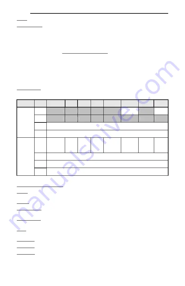
Input Instances
Table 10: Input Instances 70 and 71 Detail
Instance
Byte
Bit 7
Bit 6
Bit 5
Bit 4
Bit 3
Bit 2
Bit 1
Bit 0
70
0
Running1
Faulted
1
2
Speed Actual (Low Byte)
3
Speed Actual (High Byte)
71
0
At
Reference
Ref
from
Net
Ctrl
From
Net
Ready
Running2
(REV)
Running1
(FWD)
Warning
Faulted
1 Drive
State
2
Speed Actual (Low Byte)
3
Speed Actual (High Byte)
Input Instance Mapping Detail
Faulted: Inverter fault signal (0=not faulted, 1=faulted). Maps to inverter register 2063, bit 11 (function
code M14 / operation status word, ALM bit).
Warning: This bit is not used (it is always 0).
Running1 (FWD): Running forward status signal (0=not running forward, 1=running forward). Maps to
inverter register 2063, bit 0 (function code M14 / operation status word, FWD bit).
Running2 (REV): Running reverse status signal (0=not running reverse, 1=running reverse). Maps to
inverter register 2063, bit 1 (function code M14 / operation status word, REV bit).
Ready: Inverter ready signal (0=not ready, 1=ready). The Ready bit will be 1 whenever the Drive State
attribute (see below) is in the Ready, Enabled or Stopping state.
CtrlFromNet: This bit is not used (it is always 0).
RefFromNet: This bit is not used (it is always 0).
AtReference: Up-to-speed signal (0=not up-to-speed, 1=up-to-speed). Set to 1 if the inverter is running
(either Running1 = 1 or Running2 = 1) and both the ACC bit (bit #9) and DEC bit (bit #10) in the
operation status word (register 2063 / function code M14) are 0.


