


ICC
50
•
REV: sets bit #1 (“REV”) and clears bit #0 (“FWD”) in the operation command word (register 1799).
•
STOP: clears both bit #0 (“FWD”) and bit #1 (“REV”) in the operation command word (register
1799).
•
RESET: writes a value of “1” to register 1807, which corresponds to inverter function code S14
(alarm reset command). This will reset a faulted inverter regardless of the current operation
command mode (H30, Y98 etc.) Note that if the inverter was running (the “FWD” or “REV” buttons
were the last buttons pressed on the virtual keypad before the fault occurred), the STOP button
must be clicked prior to clicking the RESET button in order to clear the FWD and REV bits in the
operation command word. The inverter will ignore reset commands issued through register 1807 as
long as a valid run command still exists in the operation command word.
Note that the inverter will follow the FWD, REV and STOP button commands only when configured
accordingly (refer to section 3.2).
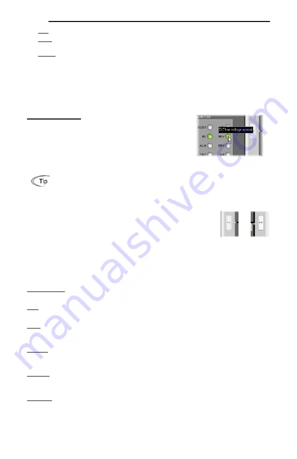
Operation status bits:
These “virtual LEDs” map to the
corresponding bits of the same name in the inverter’s operation
status word (register 2063). When a given bit in the status word is
“1”, then its corresponding indicator will be lit. The indicator will
not be lit if its status word bit is “0”. As an example, the image in
Figure 60 shows FWD (bit #0), NUV (bit #5) and RL (bit #12) ON,
and all other bits OFF.
Hovering the cursor over the virtual LEDs will bring up a tooltip which provides a brief
summary of the indicated function. Refer to Figure 61.
5.11.3 Gauge Window Navigation
Figure 62 shows the two buttons that provide for navigation of the gauge
windows. Gauge windows are displayed two at a time in the Dashboard Tab,
and by clicking the “right” or “left” buttons, the gauge windows will scroll in the
corresponding direction.
5.11.4 Gauge Window Configuration
Each of the gauge windows can be independently configured to display a user-
defined register with a variety of flexible configuration options. While the behavior and presentation may
vary slightly depending on the specific gauge chosen, all of the gauges share the following common
elements (refer to Figure 63 for an example):
Gauge Selector:
A drop-down selection box in the upper left-hand corner of the gauge window, which
allows the user to select the type of gauge that will be displayed.
Title:
A text entry box located above the gauge, in which the user can enter a descriptive gauge title
comprised of up to 16 characters.
Units:
A text entry box in which the user can enter an engineering units string comprised of up to 8
characters. This units string will be appended to all locations in the gauge window that display the
designated register’s current value.
Register:
The designated register whose value is to be reflected on the gauge. Note that only scanned
registers may be displayed in Dashboard gauges (refer to section 6.2 for a discussion of scanned
registers).
Multiplier:
The multiplier value is a floating-point number that is used to scale the raw value of a register.
As its name suggests, the multiplier value is multiplied by the designated register’s current raw value in
order to calculate the gauge’s indicated value. Negative values can also be used if desired.
Min Value:
The gauge’s minimum indicated value. Negative values can be used if desired (e.g. if a
negative Multiplier attribute is used to generate a negative indicated value). Not all gauges allow
adjustment of the min value.
Figure 61: Virtual LED Tooltips
Figure 62: Gauge
Window Navigation


