


p. 26 / 39
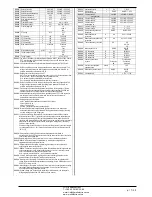
M26 – ALARM PROPERTIES
(ALAn, n=1…xxxx)
Default
Range
P26.n.01
Alarm enable
(see table)
OFF – ON
P26.n.02
Retnitive
(see table)
OFF - RIT
P26.n.03
Operating mode
(see table)
AUT-MAN
AUT
P26.n.04
Global alarm 1
(see table)
OFF – GLB1
P26.n.05
Global alarm 2
(see table)
OFF – GLB2
P26.n.06
Global alarm 3
(see table)
OFF – GLB3
P26.n.07
Step disconnection
(see table)
OFF
IMMEDIATE
SLOW
P26.n.08
Slave disconnection mode
(see table)
GENERAL - LOCAL
P26.n.09
Inhibition from input
(see table)
OFF - ON
P26.n.10
Modem call
(see table)
OFF - MDM
P26.n.11
Not shown on LCD
(see table)
OFF - NOLCD
P26.n.12
Alarm delay
(see table)
OFF/ 1-120
P26.n.13
Delay UoM
(see table)
MIN-SEC
P26.n.01
-
Alarm enabled
- General enabling of the alarm. If the alarm isn't enabled, it's as if it
doesn't exist.
P26.n.02
-
Retained alarm
- Remains in the memory even if the cause of the alarm has been
eliminated.
P26.n.03 - Operating mode
– Operating modes where the alarm can be generated.
Global alarm 1 -2 -3
- Activates the output assigned to this function.ù
P26.n.04-05-06 - Step disconnection mode
– Defines whether and how the capacitor steps
must be disconnected when the alarm is present. OFF = no disconnection, SLOW = gradual
disconnection, FAST = Immediate disconnection.
P26.n.08 - Slave disconnection mode
– Defines, for Master-Slave applications, if when this
alarm arises, the disconnection is extended to all the step of the system (GENERAL) or only to
the output of the interested panel (LOCAL).
P26.n.09 - Inhibition
- The alarm can be temporarily disabled by activating an input that can be
programmed with the Inhibit alarms function.
P26.n.10 - Modem
call
- A modem is connected as configured in setup.
P26.n.11 - No LCD
- The alarm is managed normally, but not shown on the display.
P26.n.12-13
-
Delay time
– Time delay in minutes or seconds before the alarm is generated.
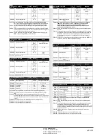
M26 – ALARM PROPERTIES
(ALAn, n=1…xxxx)
По ум.
Диапазон
P26.n.01
Включение аварийного
сигнала
(см. таблицу)
ВЫКЛ. – ВКЛ.
P26.n.02
Сохраняющийся
(см. таблицу)
OFF - RIT
P26.n.03
Режим работы
(см. таблицу)
AUT-MAN
AUT
P26.n.04
Глобальный аварийный
сигнал 1
(см. таблицу)
OFF – GLB1
P26.n.05
Глобальный аварийный
сигнал 2
(см. таблицу)
OFF – GLB2
P26.n.06
Глобальный аварийный
сигнал 3
(см. таблицу)
OFF – GLB3
P26.n.07
Отключение ступени
(см. таблицу)
ВЫКЛ.
МОМЕНТАЛЬНО
МЕДЛЕННО
P26.n.08
Режим отключения
подчиненного устройства
(см. таблицу)
ОБЩЕЕ - ЛОКАЛЬНОЕ
P26.n.09
Запрет от входа
(см. таблицу)
ВЫКЛ. – ВКЛ.
P26.n.10
Модемный вызов
(см. таблицу)
OFF - MDM
P26.n.11
Не отображается на ЖКД
(см. таблицу)
OFF - NOLCD
P26.n.12
Задержка аварийного
сигнала
(см. таблицу)
ВЫКЛ. / 1-120
P26.n.13
Ед. изм. задержки
(см. таблицу)
МИН.-СЕК.
P26.n.01
–
Аварийный сигнал включен
– Общее включение аварийного сигнала. Если
аварийный сигнал отключен, он считается не существующим.
P26.n.02
–
Сохраненный аварийный сигнал
– Остается в памяти, даже если причина
аварийного сигнала была устранена.
P26.n.03 – Режим работы
– Рабочие режимы, в которых может формироваться
аварийный сигнал.
Глобальный аварийный сигнал 1 -2 -3
– Активация выхода, соответствующего этой
функции.
P26.n.04-05-06 – Режим отключения ступени
– Определяет условия и порядок
отключения ступеней при возникновении аварийного сигнала. ВЫКЛ. = без отключения,
МЕДЛЕННО = постепенное отключение, БЫСТРО = моментальное отключение.
P26.n.08 – Режим отключения подчиненного устройства
– При работе в режиме
«ведущего-подчиненного устройства» определяет, что при возникновении этого
аварийного сигнала отключение распространяется на все ступени системы (ОБЩЕЕ) или
только на выход задействованной панели (ЛОКАЛЬНОЕ).
P26.n.09 – Запрет
– Аварийный сигнал можно временно отключить, активировав вход,
который можно запрограммировать с помощью функции запрета аварийных сигналов.
P26.n.10 – Модемный вызов
– Подключение модема в соответствии с настройкой.
P26.n.11 – Без ЖКД
– Аварийный сигнал обрабатывается обычным образом, но не
выводится на дисплей.
P26.n.12-13
–
Время задержки
– Время задержки в минутах или секундах, прежде чем
формируется аварийный сигнал.
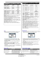
Alarms
When an alarm is generated , the display will show an alarm icon, the
code and the description of the alarm in the language selected.
If the navigation keys in the pages are pressed, the pop-up window
showing the alarm indications will disappear momentarily, to reappear
again after a few seconds.
The red LED near the alarm icon on the front panel will flash when an
alarm is active.
If enabled, the local and remote alarm buzzers will be activated.
Alarms can be reset by pressing the key
.
If the alarm cannot be reset, the problem that generated the alarm must
still be solved.
In the case of one or more alarms, the behaviour of the DCRG8 depends
on the
properties
settings of the active alarms.
Аварийные сигналы
При возникновении аварийного сигнала на экране будет показан значок аварийного
сигнала, код и описание аварийного сигнала на выбранном языке.
При нажатии на кнопки навигации на страницах всплывающее окно с аварийным
сигналом сразу исчезает и появляется вновь через несколько секунд.
При активном аварийном сигнале на передней панели устройства мигает красный
светодиод.
Местные и дистанционные звуковые оповещатели активируются, если они
задействованы.
Для сброса аварийных сигналов имеется кнопка
.
Если аварийный сигнал сбросить не получается, то проблему, вызвавшую
аварийный сигнал, все равно нужно решить.
При наличии одного и более аварийных сигналов реакция DCRG8 зависит от
настройки
свойств
активных сигналов тревоги.
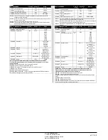
Alarm description
COD ALLARME
DESCRIZIONE
A01
Undercompensation
All the available steps are connected but the
cosphi is still more inductive than the setpoint.
A02
Overcompensation
All the steps are disconnected but the cosphi
is still more capacitive than the setpoint.
A03
Current too low
The current flowing in the current inputs is
lower than minimum measuring range.
Описание аварийных сигналов
КОД
АВАРИЙНЫЙ СИГНАЛ
ОПИСАНИЕ
A01
Недостаточная компенсация
Все доступные ступени подключены, но
индуктивность cosphi больше уставки.
A02
Чрезмерная компенсация
Все доступные ступени отключены, но емкость
cosphi больше уставки.
A03
Слишком низкий уровень тока
Ток на выходах тока меньше минимального
диапазона измерений.
Это состояние может возникать при отсутствии
ЧП
«
Профиэлектро
»
Т
. +380 44 361-62-55, 80
e-mail: [email protected]
www. profielectro.net.ua


