


p. 17 / 39
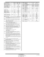
P02.14
Setpoint cosphi 2
0.95 IND
0.50 IND – 0.50 CAP
P02.15
Setpoint cosphi 3
0.95 IND
0.50 IND – 0.50 CAP
P02.16
Setpoint cosphi generating
0.95 IND
0.50 IND – 0.50 CAP
P02.17
S clearance
0.00
0 – 0.10
P02.18
Setpoint - clearance
0.00
0 – 0.10
P02.19
Step disconnection when
generating
OFF
OFF / ON
P02.20
Plant rated current
A
Aut
Aut / 1 – 30000
P02.21
Plant rated voltage
V
Aut
Aut / 100 – 60000
P02.22
Plant voltage type
LV
LV
LV / MV
MV
P02.23
VT usage
OFF
OFF
ON
P02.24
VT1 primary
V
100
50-50000
P02.25
VT1 secondary
V
100
50-500
P02.26
VT2 primary
V
100
50-50000
P02.27
VT2 secondary
V
100
50-500
P02.28
Step insertion mode
Standard
Standard
Linear
Fast
P02.29
Static switching delay
cycles
3
1-20
P02.30
Tanphi setpoint enable
OFF
OFF
ON
P02.31
Tanphi setpoint
0
-1.732 - +1.732
P02.01 -
The value of the primary current transformer. Example: with CT 800/5 set 800. If set to
OFF, after the power-up the device will prompt you to set the TA and allow direct
access to this parameter.
P02.02 -
Value of the secondary of the current transformers. Example: with CT 800/5 set 5.
P02.04
- Defines on which and on how many phases the device reads the current signal. The
wiring of current inputs must match the value set for this parameter. Supports all
possible combinations of parameter P02.06.
P02.05
- Reading the connection polarity of the CT.
AUT = Polarity is automatically detected at power up. Can only be used when working
with only one CT and when the system has no generator device.
Dir = Automatic detection disabled. Direct connection.
Rev = Automatic detection disabled. Reverse wiring (crossover).
P02.06
- Defines on which and on how many phases the device reads the voltage signal. The
wiring of voltage inputs must match the setting for this parameter. Supports all
possible combinations of parameter P02.04.
P02.07
- Value in kvar of the smallest step installed (equivalent to the step weight 1). Rated
power of the capacitor bank provided at the rated voltage specified in P02.08 and
referred to the total of the three capacitors for three-phase applications.
P02.08
- Rated plate capacitor, which is delivered in specified power P02.07. If the capacitors
are used to a tansione different (lower) than nominal, the resulting power is
automatically recalculated by the device.
P02.09
- Working frequency of the system.
Auto = automatic selection between 50 and 60 Hz at power
50Hz = fixed at 50 Hz
60 Hz = Fixed to 60 Hz
Variable = measured continuously and adjusted.
P02.10
- Minimum time that must elapse between the disconnection of one step and the
subsequent reconnection is that MAN AUT. During this time the number of the step
on the main page is shown in light gray.
P02.11 -
Connection sensitivity. This parameter sets the speed of reaction of the controller.
With small values of P02.11 regulation is fast (more accurate around the setpoint but
with more step swithchings). With high values instead we’ll have slower reactions of
regulation, with fewer switchings of the steps. The delay time of the reaction is inversely
proportional to the request of steps to reach the setpoint: waiting time = (sensitivity /
number of steps required).
Example: setting the sensitivity to 60s, if you request the insertion of one step of weight
1 are expected 60s (60/1 = 60). If instead serve a total of 4 steps will be expected 15s
(60/4 = 15).
P02.12 -
Disconnection sensitivity. Same as the previous parameter but related to
disconnection. If set to OFF the disconnection has the same reaction time of connection
set with the previous parameter.
P02.13
-Setpoint (target value) of the power factor. Value In use of standard applications.
P02.14 - P02.15
- Alternative setpoints selectable with combinations of digital inputs
programmed with the appropriate function.
P02.16
- Setpoint used when the system is generating active power to the supplier (with
negative active power / power factor ).
P02.17 - P02.18
- Tolerance around the setpoint. When the cosphi is within the range delimited
by these parameters, in AUT mode the device does not connect / disconnect steps
even if the delta-kvar is greater than the smallest step.
Note: + means “towards inductive”, - means “towards capacitive”.
P02.19
- If set to ON, when the system is giving active power provider (generation = active
power and power factor negative) all steps are disconnected.
P02.20
- Rated current of the system. Value used for the full scale of the bar graphs and for
setting the current thresholds expressed as a percentage. If set to Aut then the value of
P02.01 (CT primary) is used.
P02.21
- Rated voltage of the system. Value used for the full scale of the bar graphs and setting
the voltage thresholds expressed as a percentage. If set to Aut then the value of
P02.08 (nominal voltage capacitors) is used.
P02.22
– System voltage type. Depending on the setting of this parameter, the appropriate
wiring diagrams must be used. See at the end of the manual.
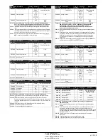
P02.11
Чувствительность
с
60
1-1000
P02.12
Отключение
чувствительность
с
ВЫКЛ.
ВЫКЛ. / 1 – 600
P02.13
Уставка cosphi 1
(стандартная)
0,95 IND
0,50 IND – 0,50 CAP
P02.14
Уставка cosphi 2
0,95 IND
0,50 IND – 0,50 CAP
P02.15
Уставка cosphi 3
0,95 IND
0,50 IND – 0,50 CAP
P02.16
Уставка cosphi
генерирующая
0,95 IND
0,50 IND – 0,50 CAP
P02.17
Уставка + допуск
0,00
0 – 0,10
P02.18
Уставка - допуск
0,00
0 – 0,10
P02.19
Отключение ступени при
генерации
ВЫКЛ.
ВЫКЛ. / ВКЛ.
P02.20
Номинальный ток
установки
A
Aut
Aut / 1 – 30000
P02.21
Номинальное напряжение
установки
В
Aut
Aut / 100 – 60000
P02.22
Тип напряжения установки
НН
НН
НН / СН
СН
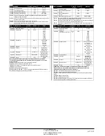
P02.23
Использование ТН
ВЫКЛ.
ВЫКЛ.
ВКЛ.
P02.24
VT1 первичная
В
100
50-50000
P02.25
VT1 вторичная
В
100
50-500
P02.26
VT2 первичная
В
100
50-50000
P02.27
VT2 вторичная
В
100
50-500
P02.28
Режим подключения
ступени
Стандартн
ый
Стандартный
Линейный
Быстрый
P02.29
Статическая задержка
переключения
циклы
3
1-20
P02.30
Включение уставки tanphi
ВЫКЛ.
ВЫКЛ.
ВКЛ.
P02.31
Уставка tanphi
0
-1,732 - +1,732
ЧП
«
Профиэлектро
»
Т
. +380 44 361-62-55, 80
e-mail: [email protected]
www. profielectro.net.ua


