


p. 28 / 39
No LCD
- The alarm is managed normally, but not shown on the display.
Delay time
– Time delay in minutes or seconds before the alarm is
generated.
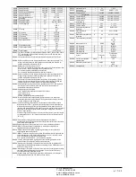
Alarm properties table
C
OD
DEFAULT ALARM PROPERTIES
Ena
bl
e
R
et
eni
tiv
e
Onl
y
in
A
U
T
m
od
e
Gl
ob
al
a
la
rm
1
Gl
ob
al
a
la
rm
2
Gl
ob
al
a
la
rm
3
Ste
p
di
sc
onn
ec
tion
m
od
e
Sl
av
e
di
sc
onne
ctio
n
m
od
e
Inhi
bi
t
M
ode
m
N
o
LC
D
D
el
ay
ti
m
e
min
se
c
A01
●
●
●
OFF GEN
●
15
●
A02
●
●
OFF GEN
●
120
●
A03
●
●
LEN GEN
●
5
●
A04
●
●
●
OFF GEN
●
120
●
A05
●
●
●
OFF GEN
●
5
●
A06
●
●
●
OFF GEN
●
15
●
A07
●
●
●
LEN LOC
●
30
●
A08
●
●
●
LEN LOC
●
30
●
A09
●
IMM GEN
●
0
●
A10
●
●
●
●
OFF GEN
●
0
●
A11
●
●
●
LEN LOC
●
3
●
A12
●
●
●
LEN LOC
●
3
●
A13
●
●
●
LEN LOC
●
3
●
A14
●
●
●
LEN LOC
●
3
●
A15
●
●
●
LEN LOC
●
3
●
A16
●
●
●
LEN LOC
●
3
●
A17
●
●
●
LEN LOC
●
10
●
A18
●
●
●
LEN LOC
●
10
●
A19
●
●
LEN GEN
●
0
●
UAx
OFF GEN
0
●
Таблица свойств аварийных сигналов
КОД
СВОЙСТВА АВАРИЙНЫХ СИГНАЛОВ ПО УМ
В
ключе
ни
е
С
охра
няе
м
ы
й
Тол
ьк
о
в
режим
е
A
U
T
Глоб
аль
ны
й
ав
ари
йн
ы
й
си
гн
ал
1
Глоб
аль
ны
й
ав
ари
йн
ы
й
си
гн
ал
2
Глоб
аль
ны
й
ав
ари
йн
ы
й
си
гн
ал
3
Ре
жи
м
отк
люче
ни
я
ступ
ен
и
Ре
жи
м
отк
люче
ни
я
подчине
нн
ог
о
ус
тр
ойств
а
За
прет
М
одем
Б
ез
ЖКД
В
рем
я
за
держк
и
м
ин
.
се
к.
A01
●
● ●
ВЫКЛ.
GEN
●
15
●
A02
●
●
ВЫКЛ. GEN
●
120
●
A03
●
●
LEN
GEN
●
5
●
A04
●
● ●
ВЫКЛ. GEN
●
120
●
A05
●
●
●
ВЫКЛ. GEN
●
5
●
A06
●
●
●
ВЫКЛ. GEN
●
15
●
A07
●
●
●
LEN
LOC
●
30
●
A08
●
●
●
LEN
LOC
●
30
●
A09
●
IMM
GEN
●
0
●
A10
●
●
● ●
ВЫКЛ. GEN
●
0
●
A11
●
● ●
LEN
LOC
●
3
●
A12
●
● ●
LEN
LOC
●
3
●
A13
●
● ●
LEN
LOC
●
3
●
A14
●
●
●
LEN
LOC
●
3
●
A15
●
●
●
LEN
LOC
●
3
●
A16
●
●
●
LEN
LOC
●
3
●
A17
●
●
●
LEN
LOC
●
10
●
A18
●
●
●
LEN
LOC
●
10
●
A19
●
●
LEN
GEN
●
0
●
UAx
ВЫКЛ. GEN
0
●
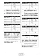
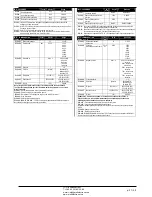
Input function table
The following table shows all the functions that can be attributed to the
INPn programmable digital inputs.
Each input can be set for an reverse function (NA - NC), delayed
energizing or de-energizing at independently set times.
Some functions require another numeric parameter, defined in the index
(x) specified by parameter
P14.n.02
.
See menu
M14 Programmable inputs
for more details.
Function
Description
OFF
Disabled input
Configurable
Free user configurable input INPx. Used for instance to
generate a user alarm UA or to count on a CNT counter.
Automatic mode
When active, switches system to AUT mode
Manual mode
When active, switches system to MAN mode
Select cosphi setpoint x
When active, selects the cosphi setpoint x (x=1…3).
Keyboard lock
Locks front keyboard.
Settings lock
Locks access to setup menu and command menu.
Alarm Inhibition
Selectively disables alarms that have
inhibit
property set
to ON.
Таблица функций входов
В следующей таблице перечислены все функции, которые могут выполнять
программируемые цифровые входы INPn.
Каждому входу может быть назначена обратная функция (NA - NC), включение с
задержкой или отключение питания в независимо задаваемое время.
Для некоторых функций требуется другой числовой параметр, определяемый
порядковым номером (x) в параметре
P14.n.02
.
См. меню
M14 Программируемые входы
.
Функция
Описание
ВЫКЛ.
Отключенный вход
Настраиваемый
Свободно настраиваемый пользователем вход INPx.
Используется, например, для формирования
пользовательского аварийного сигнала UA или
работы счетчика CNT.
Автоматический режим
При активации переводит систему в режим AUT
Ручной режим
При активации переводит систему в режим MAN
Выбор уставки cosphi x
При активации выбирается уставка cosphi x (x=1…3).
Заблокировать кнопки
Блокировка передней клавиатуры.
Блокировка настроек
Блокировка доступа к меню настройки и меню
команд.
Запрет аварийных сигналов
Выборочное отключение аварийных сигналов, у
которой свойство
inhibit
имеет значение ВКЛ.
ЧП
«
Профиэлектро
»
Т
. +380 44 361-62-55, 80
e-mail: [email protected]
www. profielectro.net.ua


