


p. 24 / 39
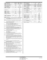
M21 – COUNTERS
(CNTn, n=1…8)
UoM
Default
Range
P21.n.01
Count source
OFF
OFF-ON-INPx-OUTx-LIMx-
REMx
P21.n.02
Channel number (x)
1
1-8
P21.n.03
Multiplier
1
1-1000
P21.n.04
Divisor
1
1-1000
P21.n.05
Description of the counter
CNTn
(Text – 16 characters)
P21.n.06
Unit of measurement
Umn
(Text – 6 characters)
P21.n.07
Reset source
OFF
OFF-ON-INPx-OUTx-LIMx-
REMx
P21.n.08
Channel number (x)
1
1-8
Note: this menu is divided into 8 sections for counters CNT1..8
P21.n.01
- Signal that increments the count (on the output side). This may be the start-up of the
DCRG8 (ON), when a threshold is exceeded (LIMx), an external input is enabled
(INPx), etc.
P21.n.02
- Channel number x with reference to the previous parameter.
P21.n.03
- Multiplier K. The counted pulses are multiplied by this value before being displayed.
P21.n.04
- Divisional K. The counted pulses are divided by this value before being displayed. If
other than 1, the counter is displayed with 2 decimal points.
P21.n.05
- Counter description. 16-character free text.
P21.n.06
- Counter unit of measurement. 6-character free text.
P21.n.07
- Signal that resets the count. As long as this signal is enabled, the count remains
zero.
P21.n.08
- Channel number x with reference to the previous parameter.
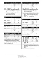
M21 – COUNTERS
(CNTn, n=1…8)
Ед.
изм.
По ум.
Диапазон
P21.n.01
Источник отсчета
ВЫКЛ.
ВЫКЛ.-ВКЛ.-INPx-OUTx-
LIMx-REMx
P21.n.02
Номер канала (x)
1
1-8
P21.n.03
Множитель
1
1-1000
P21.n.04
Делитель
1
1-1000
P21.n.05
Описание счетчика
CNTn
(Текст – 16 символов)
P21.n.06
Единица измерения
Ед. изм.
(Текст – 6 символов)
P21.n.07
Источник сброса
ВЫКЛ.
ВЫКЛ.-ВКЛ.-INPx-OUTx-
LIMx-REMx
P21.n.08
Номер канала (x)
1
1-8
Примечание. Это меню состоит из 8 частей для счетчиков CNT1..8.
P21.n.01
– Сигнал, по которому значение счетчика увеличивается на единицу (на стороне
выхода). Это может быть запуск устройства DCRG8 (ВКЛ.) при превышении
порога (LIMx), включении внешнего входа (INPx) т.д.
P21.n.02
– Номер канала x с учетом предыдущего параметра.
P21.n.03
– Множитель K. Отсчитанные импульсы умножаются на это значение перед
отображением.
P21.n.04
– Делитель K. Отсчитанные импульсы делятся на это значение перед
отображением. Если значение не 1, то значение счетчика отображается с 2
десятичными знаками.
P21.n.05
– Описание счетчика. Произвольный текст длиной 16 символов.
P21.n.06
– Единица измерения счетчика. Произвольный текст длиной 6 символов.
P21.n.07
– Сигнал, сбрасывающий счетчик. Пока сигнал действует, значение счетчика
остается 0.
P21.n.08
– Номер канала x с учетом предыдущего параметра.
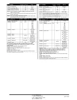
M22 - ANALOG INPUTS
(AINn, n=1…4)
UoM
Default
Range
P22.n.01
Input type
OFF
OFF
0..20mA
4….20mA
0…10V
-5V…+5V
PT100
P22.n.02
Start of scale value
0
-9999 - +9999
P22.n.03
Multiplier
x1
/100 – x1k
P22.n.04
End of scale value
0
-9999 - +9999
P22.n.05
Multiplier
x1
/100 – x1k
P22.n.06
Description
AINn
(Testo – 16 caratteri)
P22.n.07
Unit of measurement
UMn
(Testo – 6 caratteri)
Note: this menu is divided into 4 sections for the analog inputs AIN1…AIN4, available
with the EXP1004 expansion modules.
P22.n.01
- Specifies the type of sensor connected to analog input. The sensor should be
connected to the appropriate terminal for the type selected. See input module manual.
P22.n.02 and P22.n.03
- Define the value to display for a min. sensor signal, in other words at
the start of the range defined by the type (0mA, 4mA, 0V, -5V, etc.). Note: these
parameters aren't used for a type PT100 sensor.
P22.n.04 and P22.n.05
- Define the value to display for a max. sensor signal, in other words at
the end of scale of the range defined by the type (20ma, 10V, +5V, etc.). These
parameters aren't used for a type PT100 sensor.
P22.n.06
- Description of measurements associated with analog input. 16-character free text.
P22.n.07
- Unit of measurement. 6-character free text. If the input is type PT100 and the text of
the unit of measurement is
°F
, the temperature will be displayed in degrees
Fahrenheit, otherwise it will be in degrees Celsius.
Example of application: The analog input AIN3 must read a 4…20mA signal from an electronic
level sensor, that will have to be shown on the display with the descriprion ‘Reserve fuel tank
level’, with a full scale of 1500 litres.
So, we must program section 3 of this menu, that is referred to AIN3.
P22.3.01 = 4…20mA
P22.3.02 = 0
P22.3.03 = x1
P22.3.04 = 1500
P22.3.05 = x1
P22.3.06 = ‘Reserve tank level’
P22.3.07 =’ litres’
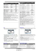
M22 - ANALOG INPUTS
(AINn, n=1…4)
Ед.
изм.
По ум.
Диапазон
P22.n.01
Тип входа
ВЫКЛ.
ВЫКЛ.
0..20 мА
4….20 мА
0…10 В
-5 В…+5 В
PT100
P22.n.02
Начальное значение
шкалы
0
-9999 - +9999
P22.n.03
Множитель
x1
/100 – x1k
P22.n.04
Конечное значение шкалы
0
-9999 - +9999
P22.n.05
Множитель
x1
/100 – x1k
P22.n.06
Описание
AINn
(Текст – 16 символов)
P22.n.07
Единица измерения
Ед. изм.
(Текст – 6 символов)
Примечание. Это меню состоит из 4 частей для аналоговых входов AIN1…AIN4,
доступных с модулями расширения EXP1004.
P22.n.01
– Определяет тип датчика, подключенного к аналоговому входу. Датчик должен
быть подключен к соответствующему контакту выбранного типа. См. руководство
к модулю входов.
P22.n.02 и P22.n.03
– Определяют значение, отображаемое для мин. сигнала датчика, то
есть, в конце диапазона, определенного типом (0 мА, 4 мА, 0 В, -5 В и т.д.).
Примечание. Эти параметры не используются для датчика типа PT100.
P22.n.04 и P22.n.05
– Определяют значение, отображаемое для макс. сигнала датчика,
то есть, в конце шкалы диапазона, определенного типом (20 мА, 10 В, +5 В и
т.д.). Эти параметры не используются для датчика типа PT100.
P22.n.06
– Описание измерений, связанных с аналоговым входом. Произвольный текст
длиной 16 символов.
P22.n.07
– Единица измерения. Произвольный текст длиной 6 символов. Если вход типа
PT100 и текст единицы измерения –
°F
, то температура отображается в градусах
Фаренгейта, иначе – в градусам Цельсия.
Пример применения:
Аналоговый вход AIN3 должен считывать сигнал 4…20 мА от
электронного уровнемера, который нужно будет выводить на дисплей с описанием
«Reserve fuel tank level» (Уровень в резервном топливном баке) при полной шкале на
1500 литров.
Итак, необходимо задать параметры в разделе 3 этого меню, то есть AIN3.
P22.3.01 = 4…20 мА
P22.3.02 = 0
P22.3.03 = x1
P22.3.04 = 1500
P22.3.05 = x1
P22.3.06 = ‘Reserve tank level’
P22.3.07 =’ litres’
M23 – ANALOG OUTPUTS
(AOUn, n=1…4)
UoM
Default
Range
P23.n.01
Output type
OFF
OFF
0..20mA
4….20mA
0…10V
-5V…+5V
P23.n.02
Reference measurement
OFF
OFF- (misure)
P23.n.03
Channel number (x)
1
OFF / 1-99
P23.n.04
Start of scale value
0
-9999 - +9999
P23.n.05
Multiplier
x1
/100 – x10k
P23.n.06
End of scale value
0
-9999 - +9999
P23.n.07
Multiplier
x1
/100 – x10k
M23 – ANALOG OUTPUTS
(AOUn, n=1…4)
Ед.
изм.
По ум.
Диапазон
P23.n.01
Тип выхода
ВЫКЛ.
ВЫКЛ.
0..20 мА
4….20 мА
0…10 В
-5 В…+5 В
P23.n.02
Контрольное измерение
ВЫКЛ.
ВЫКЛ. (измерение)
P23.n.03
Номер канала (x)
1
ВЫКЛ. / 1-99
P23.n.04
Начальное значение
шкалы
0
-9999 - +9999
P23.n.05
Множитель
x1
/100 – x10k
P23.n.06
Конечное значение шкалы
0
-9999 - +9999
P23.n.07
Множитель
x1
/100 – x10k
ЧП
«
Профиэлектро
»
Т
. +380 44 361-62-55, 80
e-mail: [email protected]
www. profielectro.net.ua


