background image


                                                                                                                                                                           p. 30 / 39


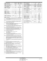
Measure table for Limits / analog outputs 


The following table lists all measures that can be associated with the 
limits (menu M20) and outputs (menu M23). 


The codes selected in the parameters P20.n.01 and P23.n.02 
correspond to the measures below. 


To facilitate comparison with the three-phase measures, some 'virtual' 
measures are provided, that contain the highest measurements across 
the three phases. These measures are identified by the presence of the 
word MAX in the measure code. 


 Example: If you want to apply a maximum limit of 10% on the content of 
5.harmonics in the current of  the system, when you have a three-phase 
current, set LIM1 with H. I MAX, with  channel no. set to 5.  The device 
will consider the highest of the harmonic content of the 5.o order among 
the three currents I L1, I L2  and I L3. 

 
Settings:  
P20.1.01 = H. I MAX  (highest current harmonic among 3 phases)  
P20.1.02 = 5               (5.th harmonic) 
P20.1.03 = max          (compare with max threshold) 
P.20.1.04 = 10           (threshold = 10%) 

…. 


Nr 

Measure code 

Description 

00 

OFF 

Measure disabled 

01 

V L1-N 

Phase voltage L1-N 

02 

V L2-N 

Phase voltage L2-N 

03 

V L3-N 

Phase voltage L3-N 

04 

I L1 

Phase current L1 

05 

I L2 

Phase current L2 

06 

I L3 

Phase current L3 

07 

V L1-L2 

Phase-to-phase voltage L1-L2 

08 

V L2-L3 

Phase-to-phase voltage L2-L3 

09 

V L3-L1 

Phase-to-phase voltage L3-L1 

10 

W L1 

Active power L1 

11 

W L2 

Active power L2 

12 

W L3 

Active power L3 

13 

var L1 

Reactive power  L1 

14 

var L2 

Reactive power L2 

15 

var L3 

Reactive power L3 

16 

VA L1 

Apparent power  L1 

17 

VA L2 

Apparent power L2 

18 

VA L3 

Apparent power L3 

19 

Hz 

Frequency 

20 

Cosphi L1 

Cosphi L1 

21 

Senphi L1 

Senphi L1 

22 

Cosphi L2 

Cosphi L2 

23 

Senphi L2 

Senphi L2 

24 

Cosphi L3 

Cosphi L3 

25 

Senphi L3 

Senphi L3 

26 

W TOT 

Total active power 

27 

var TOT 

Total reactive power 

28 

VA TOT 

Total apparent power 

29 

Cosphi TOT 

Cosphi (balanced three-phase system) 

30 

Senphi TOT 

Senphi (balanced three-phase system) 

31 

THD VLN  MAX 

THD phase voltage (max among phases) 

32 

THD I    MAX 

THD phase current (max among phases) 

33 

THD VLL MAX 

THD phase-phase voltage (max among phases) 

34 

H. VLN MAX 

Harmonic content of order n of phase voltage (maximum among 
phases) 

35 

H. I MAX 

Harmonic content of order n of phase current  (maximum among 
phases) 

36 

H. VLL MAX 

Harmonic content of order n of phase-phase voltage  (maximum 
among phases) 

37 

Cosphi MAX 

Cos-phi (max among phases) 

38 

Senphi MAX 

Sen-phi (max among phases) 

39 

VLN  MAX 

Phase voltage  (max among phases) 

40 

I MAX 

Current  (max among phases) 

41 

VLL MAX 

Phase-phase voltage (max among phases) 

42 

VLN MIN 

Phase voltage  (min among phases) 

43 

VLL MIN 

Phase-phase voltage (min among phases) 

44 

Cosphi MIN 

Cos-phi  (min among phases) 

45 

AIN 

Measure from analog inputs 

46 

CNT 

Programmable counter 


Таблица измерения пределов / аналоговых выходов


В следующей таблице перечислены все измерения, которые можно связать с 
пределами (меню M20) и выходами (меню M23). 


Коды, выбранные в параметрах P20.n.01 и P23.n.02, соответствуют измерениям 

ниже. 


Для упрощения сравнения с трехфазными измерениями, имеются некоторые 

«виртуальные» измерения, содержащие самые высокие значения по трем фазам. 

Такие измерения можно идентифицировать по слову MAX в коде измерения. 


Пример.


Необходимо применить максимальный предел 10% к 5-му коэффициенту 

гармоник в токе системы (при условии трехфазного тока), задать LIM1 значение 

H. I MAX при числе каналов – 5.


Устройство определит самый высокий 

коэффициент гармоник 5-го порядка из трех значений тока I L1, I L2 и I L3. 

 
Настройки:


P20.1.01 = H. I MAX  (самая высокая гармоника тока из 3-х фаз)


P20.1.02 = 5               (5-я гармоника) 

P20.1.03 = max          (сравнение с макс. порогом) 
P.20.1.04 = 10           (порог = 10%) 

…. 


№ 

Код измерения  Описание 

00 

OFF 

Измерение отключено 

01 

V L1-N 

Напряжение фазы L1-N 

02 

V L2-N 

Напряжение фазы L2-N 

03 

V L3-N 

Напряжение фазы L3-N 

04 

I L1 

Ток фазы L1 

05 

I L2 

Ток фазы L2 

06 

I L3 

Ток фазы L3 

07 

V L1-L2 

Междуфазное напряжение L1-L2 

08 

V L2-L3 

Междуфазное напряжение L2-L3 

09 

V L3-L1 

Междуфазное напряжение L3-L1 

10 

W L1 

Активная мощность L1 

11 

W L2 

Активная мощность L2 

12 

W L3 

Активная мощность L3 

13 

var L1 

Реактивная мощность L1 

14 

var L2 

Реактивная мощность L2 

15 

var L3 

Реактивная мощность L3 

16 

VA L1 

Кажущаяся мощность L1 

17 

VA L2 

Кажущаяся мощность L2 

18 

VA L3 

Кажущаяся мощность L3 

19 

Гц 

Частота 

20 

Cosphi L1 

Cosphi L1 

21 

Senphi L1 

Senphi L1 

22 

Cosphi L2 

Cosphi L2 

23 

Senphi L2 

Senphi L2 

24 

Cosphi L3 

Cosphi L3 

25 

Senphi L3 

Senphi L3 

26 

W TOT 

Общая активная мощность 

27 

var TOT 

Общая реактивная мощность 

28 

VA TOT 

Общая кажущаяся мощность 

29 

Cosphi TOT 

Cosphi (сбалансированная трехфазная система) 

30 

Senphi TOT 

Senphi (сбалансированная трехфазная система) 

31 

THD VLN  MAX 

Напряжение фазы КНИ (макс. междуфазное) 

32 

THD I    MAX 

Ток фазы КНИ (макс. междуфазный) 

33 

THD VLL MAX 

Напряжение фаза-фаза КНИ (макс. междуфазное) 

34 

H. VLN MAX 

Коэффициент гармоник порядка n напряжения фазы (макс. 
междуфазный) 

35 

H. I MAX 

Коэффициент гармоник порядка n тока фазы (макс. 
междуфазный) 

36 

H. VLL MAX 

Коэффициент гармоник порядка n напряжения фаза-фаза (макс. 
междуфазный) 

37 

Cosphi MAX 

Cos-phi (макс. междуфазный) 

38 

Senphi MAX 

Sen-phi (макс. междуфазный) 

39 

VLN MAX 

Напряжение фазы (макс. междуфазное) 

40 

I MAX 

Ток (макс. междуфазный) 

41 

VLL MAX 

Напряжение фаза-фаза (макс. междуфазное) 

42 

VLN MIN 

Напряжение фазы (мин. междуфазное) 

43 

VLL MIN 

Напряжение фаза-фаза (мин. междуфазное) 

44 

Cosphi MIN 

Cos-phi (мин. междуфазный) 

45 

AIN 

Измерение с аналоговых входов 

46 

CNT 

Программируемый счетчик 


ЧП

 «

Профиэлектро

» 

Т

. +380 44 361-62-55, 80 

e-mail: [email protected] 

www. profielectro.net.ua 

Summary of Contents for RPC 8BGA

Page 1: ...Main menu 4 Password access 4 Display page navigation 5 Table of display pages 5 Harmonic analysis page 7 Waveform pages 7 Expandability 8 Additional resources 9 Communication channels 9 Inputs output...

Page 2: ...y outputs o Additional analog I O for PT100 temperature current voltage Capability to operate with several units interconnected in Master Slave mode o Maximum configuration Master 8 slave o Max 32 ste...

Page 3: ...t the step is not available because its reconnection time is not yet exhausted In this case sending a command to close the step number will flash to indicate that the operation has been confirmed and...

Page 4: ...d and the access is free If instead the passwords have been enabled and defined then to get access it is necessary to enter the password first specifying the numeric code through the keypad To enable...

Page 5: ...o the display remains were it was last You can set this function in menu M01 Utility M01 Utility Table of display pages PAGES EXAMPLE Home page Power Voltage and current Step life statistics Temperatu...

Page 6: ...function is disabled For example if the limit function is not programmed the corresponding page won t be shown Event time stamp Event description Event number total Key switches between Total Partial...

Page 7: ...eric format selecting the required order through and The lower part of the screen will display a little arrow that points to the selected column and the relative percentage value of the three phases T...

Page 8: ...figuration will be saved and will become effective otherwise the mismatch will be shown at every subsequent power on of the system The present system configuration is shown in the dedicated page of th...

Page 9: ...hernet RS485 DCRG RS 485 Ethernet DCRG Ethernet COM1 COM2 COM3 Gateway DCRG Gateway Inputs outputs internal variables counters analog inputs The inputs and outputs are identified by a code and a seque...

Page 10: ...is less than the Lower threshold for the programmed delay When the measured value becomes higher than the upper setpoint after the set delay the LIM status is reset Max function the upper threshold de...

Page 11: ...protections like panel or capacitor overtemperature no voltage release harmonic protections etc The maximum possible configuration is one master with 8 slaves Example 1 application in series It is req...

Page 12: ...gical step and pairing step between logical and physical outputs of the master and the slave The program is then automatically extended to the slaves On the slave it is only necessary to set the slave...

Page 13: ...8 guaranteeing the greatest safety for the operator o High speed data transfer o IP54 front panel o Limits the possibility of unauthorized access with device config Simply hold the CX dongle up to the...

Page 14: ...e panel M18 HARMONIC PROT Harmonic protections EXP1016 module M19 MISCELLANEOUS Various settings M20 LIMIT THRESHOLDS Limit thresholds on measurements M21 COUNTERS Generic programmable counters M22 AN...

Page 15: ...to go back to the parameter selection The entered value is stored Press to save all the settings and to quit the setup menu The controller executes a reset and returns to normal operation If the user...

Page 16: ...estore delay when no key pressed If set to OFF the display will always show the last page selected manually P01 08 Default page displayed on power up and after delay P01 09 Free text with alphanumeric...

Page 17: ...number of the step on the main page is shown in light gray P02 11 Connection sensitivity This parameter sets the speed of reaction of the controller With small values of P02 11 regulation is fast more...

Page 18: ...ws to avoid regulation oscillations Set this value according to the technical characteristics closing time declared by the manufacturer of the static contactor P02 30 Enables the setting of the setpoi...

Page 19: ...the previous parameter Example If the output function is set to Alarm Axx and you want this output to be energized for alarm A31 then P04 n 02 should be set to value 31 P04 n 3 Sets the state of the...

Page 20: ...4 PROGRAMMABLE INPUTS INPn n 1 8 UdM Default Range P14 n 01 INPn input function various see Input functions table P14 n 02 Function index x OFF OFF 1 99 P14 n 03 Contact type NO NO NC P14 n 04 Delay O...

Page 21: ...U Modbus ASCII Modbus TCP P16 n 06 IP address 192 168 1 1 000 000 000 000 255 255 255 255 P16 n 07 Subnet mask 255 255 255 0 000 000 000 000 255 255 255 255 P16 n 08 IP port 1001 0 9999 Note this menu...

Page 22: ...milar P17 08 Trip threshold for the capacitors overload protection alarm A08 that will arise after a integral delay time inversely proportional to the value of the overload P17 09 Threshold beyond whi...

Page 23: ...100 P18 n 08 5 1 100 P18 n 09 7 1 100 P18 n 10 11 1 100 P18 n 11 13 1 100 P18 n 12 1 55 0 212 P18 n 13 2 55 0 212 EXP1016 P18 n 01 P18 n 02 P18 n 03 2 1 P18 n 04 P18 n 05 P18 n 06 A11 P18 n 07 A12 P18...

Page 24: ...ould be connected to the appropriate terminal for the type selected See input module manual P22 n 02 and P22 n 03 Define the value to display for a min sensor signal in other words at the start of the...

Page 25: ...Active energy Kvarh Reactive energy kVA Apparent energy P24 n 02 The quantity of energy which must accumulate for a pulse to be emitted for example 10Wh 100Wh 1kWh etc P24 n 03 Pulse duration Applicat...

Page 26: ...function P26 n 10 Modem call A modem is connected as configured in setup P26 n 11 No LCD The alarm is managed normally but not shown on the display P26 n 12 13 Delay time Time delay in minutes or sec...

Page 27: ...eshold set with P18 n 11 A17 Harmonic protection Module nr n Temperature 1 too high The temperature 1 measured by the harmonic protection module is higher than threshold set with P18 n 12 A18 Harmonic...

Page 28: ...LOC 10 A19 LEN GEN 0 UAx GEN 0 Input function table The following table shows all the functions that can be attributed to the INPn programmable digital inputs Each input can be set for an reverse fun...

Page 29: ...Energised when global alarm 2 is active Global alarm 3 Energised when global alarm 3 is active Fan Panel ventilation fan Manual mode Active when the regulator is in MAN mode Automatic mode Active when...

Page 30: ...Senphi L3 26 W TOT Total active power 27 var TOT Total reactive power 28 VA TOT Total apparent power 29 Cosphi TOT Cosphi balanced three phase system 30 Senphi TOT Senphi balanced three phase system...

Page 31: ...he backup of user settings Once the required command has been selected press to execute it The device will prompt for a confirmation Pressing again the command will be executed To cancel the command e...

Page 32: ...arameter setting P02 03 Three phase P02 04 L3 P02 06 L1 L2 P02 22 LV P02 03 P02 04 L3 P02 06 L1 L2 P02 22 Single phase wiring SINGLE PHASE CONNECTION Voltage measure 1 phase voltage reading L1 N 1 L1...

Page 33: ...2 22 FULL THREE PHASE CONNECTION WITH NEUTRAL Wiring configuration used for standard applications with full three phase voltage control Voltage measure 3 ph to n and 3 ph to ph voltage readings L1 N L...

Page 34: ...V P02 23 ON P02 03 P02 04 L3 P02 06 L1 L2 P02 22 P02 23 Configuration with MV measurement and correction Voltage measure 3 ph to ph voltage reading L1 L2 L2 L3 L3 L1 on MV side 3 L1 L2 L2 L3 L3 L1 Cur...

Page 35: ...0 90 Capacitor overload current measure 3 Readings on L1 L2 L2 L3 L3 L1 3 L1 L2 L2 L3 L3 L1 Parameter setting P02 03 Three phase P02 04 L1 L2 L3 P02 06 L1 L2 L3 P02 22 LV P02 29 Fast P02 03 P02 04 L1...

Page 36: ...01 Stepx P07 1 01 Stepx P08 1 02 Stepx P05 01 COM1 P05 02 Slave01 P05 01 COM1 P05 02 Slave02 P05 01 COM1 P05 02 Slave03 P05 01 COM1 P05 02 P05 03 P05 04 P05 05 P04 1 01 x P06 1 01 x P07 1 01 x P08 1 0...

Page 37: ...morsetti OUT 1 600V 50 60 Hz OUT 2 OUT 3 OUT 4 OUT 5 OUT 6 OUT 7 OUT 8 SLOT 1 SLOT 2 SLOT 3 SLOT 4 Dimensioni meccaniche e foratura pannello mm 380 44 361 62 55 80 e mail info profielectro net ua www...

Page 38: ...age 415V 415 Rated current AC1 5A 250V AC15 1 5A 415V AC1 5A 250 AC15 1 5A 415 Real time clock Energy storage Back up capacitors Operating time without supply voltage About 12 15 days 12 15 Insulation...

Page 39: ...phase neutral voltage 300V 300 Rev Date Notes 00 30 10 2012 First release 00 30 10 2012 01 28 01 2013 Added Tanfi parameters P02 30 e P02 31 01 28 01 2013 tanfi P02 30 P02 31 380 44 361 62 55 80 e ma...

Reviews: