background image


                                                                                                                                                                           p. 11 / 39


User Alarms (UAx) 


The user has the possibility to define a maximum of 8 programmable 
alarms (UA1…UA8). 


For each alarm, it is possible to define: 

o


the 

source

 that is the condition that generates the alarm,  

o


the 

text

 of the message that must appear on the screen when this 

condition is met. 

o


The 

properties

 of the alarm (just like for standard alarms), that is in 

which way that alarms interacts with the power factor correction. 


The condition that generates the alarm can be, for instance, the 
overcoming of a threshold. In this case, the source will be one of the limit 
thresholds LIMx. 


If instead, the alarm must be displayed depending on the status of an 
external digital input, then the source will be an INPx. 


For every alarm, the user can define a free message that will appear on the 
alarm page. 


The properties of the user alarms can be defined in the same way as the 
normal alarms. You can choose whether a certain alarm will disconnect the 
steps, close the global alarm output, etc. See chapter 

Alarm properties


When several alarms are active at the same time, they are displayed 
sequentially, and their total number is shown on the status bar. 


To reset one alarm that has been programmed with latch, use the 
dedicated command in the commands menu. 


For details on alarm programming and definition, refer to setup menu 
M26Ошибка! Источник ссылки не найден. 


Пользовательские аварийные сигналы (UAx) 


Пользователь может определить не более 8 программируемых аварийных 
сигналов (UA1…UA8). 


Для каждого аварийного сигнала можно определить: 

o


источник, 

являющийся условием создания аварийного сигнала,  

o


текст

 сообщения, появляющегося на экране при выполнении 

условия, 

o


свойства

 аварийного сигнала (подобные стандартным аварийным 

сигналам), то есть то, как аварийные сигналы воздействуют на 

коррекцию коэффициента мощности. 


Например, условием, создающим аварийный сигнал, является превышение 

порога. В этом случае источником будет один из пороговых пределов LIMx. 


Если, наоборот, в зависимости от состояния внешнего цифрового входа, 

требуется отобразить аварийный сигнал, то источником будет INPx. 


Для каждого аварийного сигнала пользователь может определить 

произвольное сообщение, которое будет показано на странице аварийных 
сигналов. 


Свойства пользовательских аварийных сигналов можно определить таким 
же образом, как свойства обычных сигналов. Можно задать отключение 

ступеней по определенным сигналам, глобальное закрытие выходов, и так 
далее. См. раздел «

Свойства аварийных сигналов

». 


При активации нескольких аварийных сигналов одновременно они 

отображаются последовательно, и общее количество показывается в 
строке состояния. 


Чтобы сбросить один аварийный сигнал с запрограммированной 
фиксацией, в меню команд имеется специальная команда. 


Подробную информацию о программировании и определении аварийных 
сигналов см. в меню настройки M26

Ошибка! Источник ссылки не найден.


Master-Slave configuration 


To further extend the flexibility of use of DCRG8 it is available the Master-
Slave function, which allows, for plants with high installed power,  to 
compose a series of panels in cascade, each with its own controller and 
associated capacitor banks.


This solution allows to expand in a modular way the power factor correction 
system, in case it becomes necessary because of the increased needs of 
the plant. 


In this configuration, measurements are made only from the first controller 
(Master) which controls a maximum of 32 

logical

 steps,  that are then sent 

to all the slave units.


The slave controllers drive their steps as indicated by the master, while 
performing the ‘local’ protections like panel or capacitor overtemperature, 
no-voltage release, harmonic protections etc.


The maximum possible configuration is one master with 8 slaves.


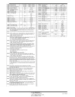
Example 1 (application in series):


It is required to create a system with 18 step of 40kvar each, divided into 
three identical panels with 6 step (240kvar) each. For each panel, the 8 relay 
outputs of the controller are used as follows: the first six for the steps (OUT1. 
.6), the seventh for the cooling fan (OUT7) and the last for the alarm (OUT8). 
On the master panel we will define 18 logical step of 50kvar. The steps from 1 
to 6 will be 'mapped' on the outputs OUT1 .. 6 of the master, those from 7 to 
12 on the outputs OUT1 .. 6 of slave1 and finally the steps from 13 to 18 on 
the outputs OUT1 .. 6 of the slave 2. In this case, the parameter 

P02.07 

Smallest step power 

will have to be set (on the master) to 40kvar. 


Programming of the master: 

PARAMETER 

VALUE 

DESCRIPTION 

P02.07  

40 

40 kvar 

P03.01.01

P03.18.01 

All the 18 logic steps are 40kvar  

P04.01.01…P04.06.01 

Step 1…6 

Outputs OUT1…OUT6 of the master are activated 
by logical steps 1…6. 

P04.07101 

Fan 

OUT7 of the master controls cooling fan 

P04.08.01 

All glb 1 

OUT8 of the master controls global alarm 1 

P05.01 

COM1 

COM port used for the link 

P05.02 

Master 

Role of master 

P05.03…P05.04 

ON 

Enables slave 1 and slave 2 

P06.01.01…P06.06.01 

Step 7…12 

Outputs OUT1…OUT6 of slave 1 are activated by 
logical steps 7…12. 

P06.07.01 

Fan 

OUT7 of slave 1 controls cooling fan 

P06.08.01 

All glb 1 

OUT8 of slave 1  controls global alarm 1 

P07.01.01…P07.06.01 

Step 13…18  Outputs OUT1…OUT6 of slave 2 are activated by 

logical steps 13…18. 

P07.07.01 

Fan 

OUT7 of slave 2 controls cooling fan 

P07.08.01 

All glb 1 

OUT8 of slave 2 controls global alarm 1 


Programming of slave 1: 

P05.02 

Slave1 

Role: slave1 


Конфигурация «Ведущее-подчиненное устройство» 


Для обеспечения дополнительной универсальности DCRG8, доступна 

функция «ведущее-подчиненное устройство». Благодаря ей на объектах с 
высокой установленной мощностью можно объединять несколько приборов 

в каскад, каждый со своим собственным регулятором и связанными 
батареями конденсаторов.


Это решение позволяет добиться модульного расширения системы 
корректировки коэффициента мощности по мере увеличения потребностей 

установки. 


В такой конфигурации измерения выполняет только первый регулятор 

(ведущий), управляющий максимально 32 

логическими

 ступенями, которые 

затем передаются всем подчиненным устройствам.


Ступени на подчиненных устройствах задаются ведущим прибором. При 
этом подчиненные устройства обеспечивают «местную» защиту, например 

от перегрева панели или конденсатора, от отсутствия напряжения, 
гармонических искажений и т.д.


В максимально возможной конфигурации присутствует одно ведущее 

устройство и 8 подчиненных.


Пример 1 (последовательное применение):


Необходимо создать систему с 18 ступенями по 40 квар каждая, с 

разделением на три идентичные панели по 6 ступеней (240 квар).


Для 

каждой панели 8 релейных выходов используются следующим образом: 

первые шесть для ступеней (OUT1. .6), седьмой для вентилятора 
охлаждения (OUT7) и последний для аварийного сигнала (OUT8).


На ведущей 

панели задается 18 логических ступеней по 50 квар.


Ступени с 1 по 6 

назначаются выходам OUT1 ..


6 ведущего устройства, ступени с 7 по 12 – 

выходам OUT1 ..


6 подчиненного устройства 1 и, наконец, ступени с 13 по 

18 присваиваются выходам OUT1 ..


6 подчиненного устройства 2.


В этом 

случае параметру 

P02.07 Smallest step power (Наименьшая мощность 

ступени) 

необходимо будет присвоить значение 40 квар (на ведущем 

устройстве).


Программирование ведущего устройства:


ПАРАМЕТР 

ЗНАЧЕНИЕ  ОПИСАНИЕ 

P02.07


40 

40 квар 

P03.01.01

P03.18.01


Все 18 логических ступеней по 40 квар  

P04.01.01…P04.06.01


Step 1…6 

Выходы OUT1…OUT6 ведущего устройства 
активируются логическими ступенями 1…6. 

P04.07101


Вентилятор  OUT7 ведущего устройства управляет 

вентилятором охлаждения 

P04.08.01


All glb 1 

OUT8 ведущего устройства управляет 
глобальным аварийным сигналом 1 

P05.01


COM1 

COM-порт, используемый для связи 

P05.02


Master 

Роль ведущего устройства 

P05.03…P05.04


ON 

Включение подчиненного устройства 1 и 
подчиненного устройства 2 

P06.01.01…P06.06.01


Step 7…12 

Выходы OUT1…OUT6 подчиненного 
устройства 1 активируются логическими 
ступенями 7…12. 

P06.07.01


Fan 

OUT7 подчиненного устройства 1 управляет 
вентилятором охлаждения 

P06.08.01


All glb 1 

OUT8 подчиненного устройства 1 управляет 

ЧП

 «

Профиэлектро

» 

Т

. +380 44 361-62-55, 80 

e-mail: [email protected] 

www. profielectro.net.ua 

Summary of Contents for RPC 8BGA

Page 1: ...Main menu 4 Password access 4 Display page navigation 5 Table of display pages 5 Harmonic analysis page 7 Waveform pages 7 Expandability 8 Additional resources 9 Communication channels 9 Inputs output...

Page 2: ...y outputs o Additional analog I O for PT100 temperature current voltage Capability to operate with several units interconnected in Master Slave mode o Maximum configuration Master 8 slave o Max 32 ste...

Page 3: ...t the step is not available because its reconnection time is not yet exhausted In this case sending a command to close the step number will flash to indicate that the operation has been confirmed and...

Page 4: ...d and the access is free If instead the passwords have been enabled and defined then to get access it is necessary to enter the password first specifying the numeric code through the keypad To enable...

Page 5: ...o the display remains were it was last You can set this function in menu M01 Utility M01 Utility Table of display pages PAGES EXAMPLE Home page Power Voltage and current Step life statistics Temperatu...

Page 6: ...function is disabled For example if the limit function is not programmed the corresponding page won t be shown Event time stamp Event description Event number total Key switches between Total Partial...

Page 7: ...eric format selecting the required order through and The lower part of the screen will display a little arrow that points to the selected column and the relative percentage value of the three phases T...

Page 8: ...figuration will be saved and will become effective otherwise the mismatch will be shown at every subsequent power on of the system The present system configuration is shown in the dedicated page of th...

Page 9: ...hernet RS485 DCRG RS 485 Ethernet DCRG Ethernet COM1 COM2 COM3 Gateway DCRG Gateway Inputs outputs internal variables counters analog inputs The inputs and outputs are identified by a code and a seque...

Page 10: ...is less than the Lower threshold for the programmed delay When the measured value becomes higher than the upper setpoint after the set delay the LIM status is reset Max function the upper threshold de...

Page 11: ...protections like panel or capacitor overtemperature no voltage release harmonic protections etc The maximum possible configuration is one master with 8 slaves Example 1 application in series It is req...

Page 12: ...gical step and pairing step between logical and physical outputs of the master and the slave The program is then automatically extended to the slaves On the slave it is only necessary to set the slave...

Page 13: ...8 guaranteeing the greatest safety for the operator o High speed data transfer o IP54 front panel o Limits the possibility of unauthorized access with device config Simply hold the CX dongle up to the...

Page 14: ...e panel M18 HARMONIC PROT Harmonic protections EXP1016 module M19 MISCELLANEOUS Various settings M20 LIMIT THRESHOLDS Limit thresholds on measurements M21 COUNTERS Generic programmable counters M22 AN...

Page 15: ...to go back to the parameter selection The entered value is stored Press to save all the settings and to quit the setup menu The controller executes a reset and returns to normal operation If the user...

Page 16: ...estore delay when no key pressed If set to OFF the display will always show the last page selected manually P01 08 Default page displayed on power up and after delay P01 09 Free text with alphanumeric...

Page 17: ...number of the step on the main page is shown in light gray P02 11 Connection sensitivity This parameter sets the speed of reaction of the controller With small values of P02 11 regulation is fast more...

Page 18: ...ws to avoid regulation oscillations Set this value according to the technical characteristics closing time declared by the manufacturer of the static contactor P02 30 Enables the setting of the setpoi...

Page 19: ...the previous parameter Example If the output function is set to Alarm Axx and you want this output to be energized for alarm A31 then P04 n 02 should be set to value 31 P04 n 3 Sets the state of the...

Page 20: ...4 PROGRAMMABLE INPUTS INPn n 1 8 UdM Default Range P14 n 01 INPn input function various see Input functions table P14 n 02 Function index x OFF OFF 1 99 P14 n 03 Contact type NO NO NC P14 n 04 Delay O...

Page 21: ...U Modbus ASCII Modbus TCP P16 n 06 IP address 192 168 1 1 000 000 000 000 255 255 255 255 P16 n 07 Subnet mask 255 255 255 0 000 000 000 000 255 255 255 255 P16 n 08 IP port 1001 0 9999 Note this menu...

Page 22: ...milar P17 08 Trip threshold for the capacitors overload protection alarm A08 that will arise after a integral delay time inversely proportional to the value of the overload P17 09 Threshold beyond whi...

Page 23: ...100 P18 n 08 5 1 100 P18 n 09 7 1 100 P18 n 10 11 1 100 P18 n 11 13 1 100 P18 n 12 1 55 0 212 P18 n 13 2 55 0 212 EXP1016 P18 n 01 P18 n 02 P18 n 03 2 1 P18 n 04 P18 n 05 P18 n 06 A11 P18 n 07 A12 P18...

Page 24: ...ould be connected to the appropriate terminal for the type selected See input module manual P22 n 02 and P22 n 03 Define the value to display for a min sensor signal in other words at the start of the...

Page 25: ...Active energy Kvarh Reactive energy kVA Apparent energy P24 n 02 The quantity of energy which must accumulate for a pulse to be emitted for example 10Wh 100Wh 1kWh etc P24 n 03 Pulse duration Applicat...

Page 26: ...function P26 n 10 Modem call A modem is connected as configured in setup P26 n 11 No LCD The alarm is managed normally but not shown on the display P26 n 12 13 Delay time Time delay in minutes or sec...

Page 27: ...eshold set with P18 n 11 A17 Harmonic protection Module nr n Temperature 1 too high The temperature 1 measured by the harmonic protection module is higher than threshold set with P18 n 12 A18 Harmonic...

Page 28: ...LOC 10 A19 LEN GEN 0 UAx GEN 0 Input function table The following table shows all the functions that can be attributed to the INPn programmable digital inputs Each input can be set for an reverse fun...

Page 29: ...Energised when global alarm 2 is active Global alarm 3 Energised when global alarm 3 is active Fan Panel ventilation fan Manual mode Active when the regulator is in MAN mode Automatic mode Active when...

Page 30: ...Senphi L3 26 W TOT Total active power 27 var TOT Total reactive power 28 VA TOT Total apparent power 29 Cosphi TOT Cosphi balanced three phase system 30 Senphi TOT Senphi balanced three phase system...

Page 31: ...he backup of user settings Once the required command has been selected press to execute it The device will prompt for a confirmation Pressing again the command will be executed To cancel the command e...

Page 32: ...arameter setting P02 03 Three phase P02 04 L3 P02 06 L1 L2 P02 22 LV P02 03 P02 04 L3 P02 06 L1 L2 P02 22 Single phase wiring SINGLE PHASE CONNECTION Voltage measure 1 phase voltage reading L1 N 1 L1...

Page 33: ...2 22 FULL THREE PHASE CONNECTION WITH NEUTRAL Wiring configuration used for standard applications with full three phase voltage control Voltage measure 3 ph to n and 3 ph to ph voltage readings L1 N L...

Page 34: ...V P02 23 ON P02 03 P02 04 L3 P02 06 L1 L2 P02 22 P02 23 Configuration with MV measurement and correction Voltage measure 3 ph to ph voltage reading L1 L2 L2 L3 L3 L1 on MV side 3 L1 L2 L2 L3 L3 L1 Cur...

Page 35: ...0 90 Capacitor overload current measure 3 Readings on L1 L2 L2 L3 L3 L1 3 L1 L2 L2 L3 L3 L1 Parameter setting P02 03 Three phase P02 04 L1 L2 L3 P02 06 L1 L2 L3 P02 22 LV P02 29 Fast P02 03 P02 04 L1...

Page 36: ...01 Stepx P07 1 01 Stepx P08 1 02 Stepx P05 01 COM1 P05 02 Slave01 P05 01 COM1 P05 02 Slave02 P05 01 COM1 P05 02 Slave03 P05 01 COM1 P05 02 P05 03 P05 04 P05 05 P04 1 01 x P06 1 01 x P07 1 01 x P08 1 0...

Page 37: ...morsetti OUT 1 600V 50 60 Hz OUT 2 OUT 3 OUT 4 OUT 5 OUT 6 OUT 7 OUT 8 SLOT 1 SLOT 2 SLOT 3 SLOT 4 Dimensioni meccaniche e foratura pannello mm 380 44 361 62 55 80 e mail info profielectro net ua www...

Page 38: ...age 415V 415 Rated current AC1 5A 250V AC15 1 5A 415V AC1 5A 250 AC15 1 5A 415 Real time clock Energy storage Back up capacitors Operating time without supply voltage About 12 15 days 12 15 Insulation...

Page 39: ...phase neutral voltage 300V 300 Rev Date Notes 00 30 10 2012 First release 00 30 10 2012 01 28 01 2013 Added Tanfi parameters P02 30 e P02 31 01 28 01 2013 tanfi P02 30 P02 31 380 44 361 62 55 80 e ma...

Reviews: