


p. 18 / 39
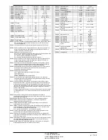
P02.23 .... P02.27
– Data of VTs eventually used in the wiring diagrams.
P02.28 -
Selecting mode of steps insertion
Standard mode - Normal operation with free selection of the steps
Linear mode - the steps are connected in progression from left towards right only
following the step number and according to the LIFO (Last In First Out) logic. The
controller will not connect a step when the system steps are of different ratings and by
connecting the next step, the set-point value would be exceeded.
P02.29
- After having closed one step output, the measure acquisition is suspended for the
number of periods (cycles) specified by this parameter, in order to allow the external
static contactor to connect the capacitors. This function allows to avoid regulation
oscillations. Set this value according to the technical characteristics (closing time)
declared by the manufacturer of the static contactor.
P02.30 –
Enables the setting of the setpoint as Tangent of displacement phase angle (Tanphi)
instead of Cosinus (Cosphi). Used as a reference by the energy suppliers of some
european countries.
P02.31 –
Value of the Tnaphi setpoint. Negative values of Tanphi correspond to capacitive
Cophi..
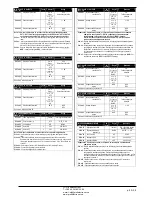
P02.01 –
Значение для первичной обмотки трансформатора тока. Пример: при ТТ 800/5
задать 800. Если выбрано ВЫКЛ., то после включения устройство предложит
задать TA и предоставит прямой доступ к этому параметру.
P02.02 –
Значение для вторичной обмотки трансформаторов тока. Пример: при ТТ 800/5
задать 5.
P02.04
– Определяет фазы и их количество для считывания сигнала тока устройством.
Подключение входов тока должно соответствовать значению, установленному
для этого параметра. Поддерживаются все возможные сочетания параметра
P02.06.
P02.05
– Считывание полярности подключения ТТ.
AUT = полярность определяется автоматически в момент включения. Может
использоваться только при работе с одним ТТ и когда система не является
генерирующим устройством.
Dir = автоматическое определение отключено. Прямое подключение.
Rev = автоматическое определение отключено. Обратное подключение
(кроссоверное).
P02.06
– Определяет фазы и их количество для считывания сигнала напряжения
устройством. Подключение входов напряжения должно соответствовать
настройке этого параметра. Поддерживаются все возможные сочетания
параметра P02.04.
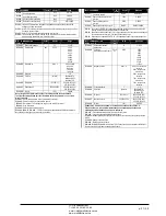
P02.07
– Значение в квар самой низкой заданной ступени (эквивалентно весу ступени 1).
Номинальная мощность батареи конденсаторов при условии заданного
номинального напряжения в параметре P02.08 и на основе трех конденсаторов
для трехфазных установок.
P02.08
– Номинальное напряжение конденсатора, обеспечиваемое с заданной
мощностью P02.07. Если используются конденсаторы с отличным (меньшим) по
сравнению с номиналом напряжением, то устройство автоматически
пересчитывает результирующую мощность.
P02.09
– Рабочая частота системы.
Auto = автоматический выбор из 50 и 60 Гц при мощности
50Гц = фиксировано 50 Гц
60Гц = фиксировано 60 Гц
Переменная = измеряется постоянно и подстраивается.
P02.10
– Минимальное время, которое должно пройти между отключением одной ступени
и последующим переподключением, то есть MAN AUT. В это время номер
ступени отображается на главной странице светло-серым цветом.
P02.11 –
Чувствительность подключения. Этот параметр определяет скорость реакции
регулятора. При небольших значениях P02.11 регулирование происходит быстро
(ближе к уставке, но с более интенсивным переключением ступеней). При более
высоких значениях наоборот – реакция регулирования медленнее при меньшем
переключении ступеней. Время задержки реакции обратно пропорционально
запросу ступеней на достижение уставок: время ожидания = (чувствительность /
необходимое количество ступеней).
Пример: при установке чувствительности на уровне 60 с, для выполнения
запроса на добавление одной ступени весом 1 потребуется 60 с (60/1 = 60).
Для
обработки 4 ступеней потребуется 15 с (60/4 = 15).
P02.12 –
Чувствительность отключения. Аналогично предыдущему параметру, но
относится к отключению. Если задано ВЫКЛ., то отключение происходит с тем же
временем реакции подключения, которое задано в предыдущем параметре.
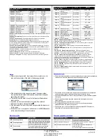
P02.13
– Уставка (целевое значение) коэффициента мощности. Значение для
стандартных условий.
P02.14 - P02.15
– Альтернативные уставки, выбираемые по сочетаниям цифровых
выходов, запрограммированных с соответствующей функцией.
P02.16
– Уставка, используемая в случае генерирования системой активной энергии для
источника (с отрицательным коэффициентом / активной мощности ).
P02.17 - P02.18
– Допуск уставки. Если cosphi в пределах диапазона, ограниченного
этими параметрами, в режиме AUT устройство не подключает / не отключает
ступени, даже если дельта-квар больше самой малой ступени.
Примечание. + означает «к индуктивной», - означает «к емкостной».
P02.19
– Если выбрано ВКЛ., когда система выдает активную мощность (генерация =
активная мощность и отрицательный коэффициент мощности), все ступени
отключаются.
P02.20
- Номинальный ток системы. Значение, используемое для полной шкалы
гистограмм и для установки порогов по току, выражено в процентах. Если
выбрано Aut, то используется значение параметра P02.01 (ТТ первичная).
P02.21
– Номинальное напряжение системы. Значение, используемое для полной шкалы
гистограмм и для установки порогов по напряжению, выражено в процентах. Если
выбрано Aut, то используется значение параметра P02.08 (номинальное
напряжение конденсаторов).
P02.22
– Тип напряжения системы. В зависимости от настройки этого параметра следует
использовать соответствующие схемы подключения. См. в конце руководства.
P02.23 .... P02.27
– Данные ТН, используемые в конечном счете в схемах подключения.
P02.28 –
Выбор режима добавления ступеней
Стандартный режим – обычный режим работы с произвольным выбором
ступеней
Линейный режим – ступени подключаются последовательно слева направо по
номерам ступеней и в соответствии с логикой LIFO (Last In First Out). Регулятор не
подключает ступень, если ступени системы имеют разный номинал и если
подключение следующей ступени приведет к превышению уставки.
P02.29
– После закрытия выхода одной ступени прием показаний приостанавливается на
число периодов (циклов), заданных этим параметром, с тем, чтобы внешний
статический контактор мог подключить конденсаторы. Эта функция позволяет
предотвратить колебание регулирования. Задавайте это значение в соответствии
с техническими характеристиками (время закрытия), заявленными
производителем статического контактора.
P02.30 –
Определяет уставку в виде тангенса угла сдвига фазы (Tanphi) вместо косинуса
(Cosphi). Используется в качестве эталонного значения поставщиками энергии в
некоторых европейских странах.
P02.31 –
Значение уставки tanphi. Отрицательные значения tanphi соответствуют
емкостному значению cophi.
ЧП
«
Профиэлектро
»
Т
. +380 44 361-62-55, 80
e-mail: [email protected]
www. profielectro.net.ua


