background image


Chapter 5.  Installing options

 81

Setting SCSI IDs:  

Each SCSI device connected to a SCSI controller must have a 

unique SCSI ID. This ID enables the SCSI controller to identify the device and ensure 
that different devices on the same SCSI channel do not attempt to transfer data 
simultaneously. SCSI devices that are connected to different SCSI channels can have 
duplicate SCSI IDs. Refer to the information that is provided with the device for 
instructions on setting its SCSI ID. With a SCSI adapter installed in your computer, 
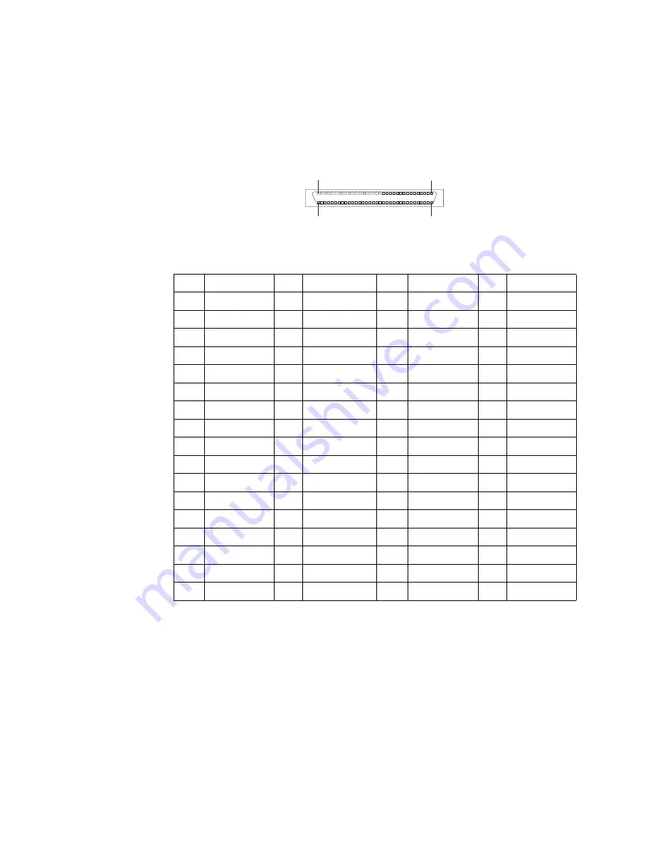
you can use its 68-pin SCSI connector to connect different types of SCSI devices.

To install SCSI devices, you must have an optional PCI SCSI adapter installed. Refer 
to the information that is provided with the device for instructions to set its SCSI ID.

Table 10. SCSI connector-pin assignments. 

Pin

Signal

Pin

Signal

Pin

Signal

Pin

Signal

1

+DB (12)

18

TERMPWR

35

–DB (12)

52

TERMPWR

2

+DB (13)

19

RESERVED

36

–DB (13)

53

GROUND

3

+DB (14)

20

GROUND

37

–DB (14)

54

GROUND

4

+DB (15)

21

+ATN

38

–DB (15)

55

–ATN

5

+DB (P1)

22

GROUND

39

–DB (P1)

56

GROUND

6

+DB (0)

23

+BSY

40

–DB (0)

57

–BSY

7

+DB  (1)

24

+ACK

41

–DB (1)

58

–ACK

8

+DB (2)

25

+RST

42

–DB (2)

59

–RST

9

+DB  (3)

26

+MSG

43

–DB (3)

60

–MSG

10

+DB (4)

27

+SEL

44

–DB (4)

61

–SEL

11

+DB (5)

28

+C/D

45

–DB (5)

62

–C/D

12

+DB (6)

29

REQ

46

–DB (6)

63

–REQ

13

+DB (7)

30

+I/O

47

–DB (7)

64

–I/O

14

+DB (P)

31

+DB (8)

48

–DB (P)

65

–DB (8)

15

GROUND

32

+DB (9)

49

GROUND

66

–DB (9)

16

DIFFSENS

33

+DB (10)

50

GROUND

67

–DB (10)

17

TERMPWR

34

+DB (11)

51

TERMPWR

68

–DB (11)

34

1

68

35

Summary of Contents for INTELLISTATION E PRO 6204

Page 1: ...computer at http www ibm com pc support on the IBM Web site User s Guide applications to run on your User s Guide Types 6204 and 6214 IntelliStation E Pro Go to the Solving Problems chapter Start the...

Page 2: ...omputer to determine the cause of the problem and the action to take Flash the latest levels of BIOS and download the latest level of diagnostics You can download this code at http www ibm com pc supp...

Page 3: ...IBM IBM IntelliStation E Pro User s Guide...

Page 4: ...tober 2001 Copyright International Business Machines Corporation 2000 2001 All rights reserved US Government Users Restricted Rights Use duplication or disclosure restricted by GSA ADP Schedule Contra...

Page 5: ...ing 11 Air circulation 12 Electrical outlets and cable lengths 12 Moving the stabilizing feet 12 Setting the voltage selection switch 13 Connecting computer cables 13 Recording important numbers 15 Ru...

Page 6: ...el 41 Tower model 54 Major components of the tower model 54 System and PCI extender boards 55 Installing options in a tower model 58 Connecting external options 73 Input output connector locations 74...

Page 7: ...he license agreement 121 Appendix E Warranty information 123 Warranty period 123 Warranty service and support 123 Before you call for service 123 Calling for service 124 IBM Statement of Limited Warra...

Page 8: ...vi IBM IntelliStation E Pro User s Guide...

Page 9: ...t eerst de veiligheidsvoorschriften Ennen kuin asennat t m n tuotteen lue turvaohjeet kohdasta Safety Information Avant d installer ce produit lisez les consignes de s curit Vor der Installation diese...

Page 10: ...ces Electrical current from power telephone and communication cables is hazardous To avoid a shock hazard Do not connect or disconnect any cables or perform installation maintenance or reconfiguration...

Page 11: ...sassemble Dispose of the battery as required by local ordinances or regulations Statement 3 CAUTION When laser products such as CD ROMs DVD drives fiber optic devices or transmitters are installed not...

Page 12: ...on the device and the power switch on the power supply do not turn off the electrical current supplied to the device The device also might have more than one power cord To remove all electrical curre...

Page 13: ...any part that has the following label attached Hazardous voltage current and energy levels are present inside any component that has this label attached There are no serviceable parts inside these com...

Page 14: ...xii IBM IntelliStation E Pro User s Guide...

Page 15: ...ough Access IBM contains information and instructions for installing and configuring small computer systems interface SCSI device drivers and devices Safety Information This publication accessible thr...

Page 16: ...xiv IBM IntelliStation E Pro User s Guide...

Page 17: ...u have access to the Internet you can obtain up to date information about your computer and other IBM computer products at http www ibm com pc intellistation on the World Wide Web Refer to the followi...

Page 18: ...ight approximately 9 1 kg 20 lb when fully configured or 6 8 kg 15 0 lb minimum Integrated functions 10BASE T 100BASE TX Ethernet controller on the system board with RJ 45 Ethernet port Two serial por...

Page 19: ...atrox G450 AGP adapter with 16 MB SDRAM video memory NVidia Quadro2 Pro AGP adapter with 64 MB SDRAM video memory Size and weight Height 445 mm 17 5 in Depth 498 mm 19 6 in Width 165 mm 6 5 in Weight...

Page 20: ...tracking and recovery tool It provides features that you can use to restore your system if your computer becomes damaged unusable or unstartable IBM Backup and Restore provides a link to the Web site...

Page 21: ...e Selections CD The Software Selections CD contains application programs and support software for use with your computer such as The Product Recovery Program is on a hidden hard disk drive partition D...

Page 22: ...your computer Some of the features include Wake on LAN Remote Administration and System Migration Assistant See Managing your computer on a network on page 21 for more information Integrated network...

Page 23: ...nd power interface ACPI Power on self test POST Synchronous dynamic random access memory SDRAM with serial presence detect SPD Availability features Advanced Desktop Management Interface DMI features...

Page 24: ...e activity light indicates when the CD ROM drive is in use Hard disk drive activity light Power on light Power control button CD eject button CD ROM drive activity light Diskette drive activity light...

Page 25: ...is light is on the Ethernet speed is 100 Mbps When this light is off the Ethernet speed is 10 Mbps Ethernet transmit receive activity when this light is on there is activity between the computer and t...

Page 26: ...10 IBM IntelliStation E Pro User s Guide...

Page 27: ...ts can also affect the way you arrange your workspace Comfort The following guidelines will help you decide what working position suits you best Choose a chair to reduce fatigue from sitting in the sa...

Page 28: ...51 mm 2 in of air space is sufficient Also make sure the vented air is not blowing on someone else Electrical outlets and cable lengths The location of electrical outlets and the length of device powe...

Page 29: ...er Setting the voltage selection switch If you have a desktop model check the position of the voltage selection switch located beside the power cord connector Use a ballpoint pen to slide the switch i...

Page 30: ...ard cable to the keyboard connector and connect the mouse cable to the mouse connector REQTEXT 2 Connect any additional devices you have Connect a printer or parallel device to the parallel connector...

Page 31: ...ing your computer for the first time the Microsoft Windows setup program runs automatically when you start the computer The program will prompt you to make choices or type information If you need more...

Page 32: ...gister on the World Wide Web Note The Register program that starts through Access IBM or the IBM Registration icon will enable you to print the registration information and provide a mailing address i...

Page 33: ...s World Wide Web site to obtain the updates Additional information about operating systems is posted periodically at http www ibm com pc support on the World Wide Web Product Recovery Program The Pro...

Page 34: ...Recovery Repair diskette 1 From the Access IBM menu click Protect data 2 Click Creating emergency diskettes 3 Click Recovery Repair diskette 4 Follow the instructions on the screen Creating a Norton A...

Page 35: ...BM Setup Utility program on page 27 and Using the SCSISelect Utility program some models on page 32 During startup you might not see Hit F2 if you want to run SETUP If you want to see the prompt see i...

Page 36: ...by your monitor might cause the screen to become unreadable and could damage the monitor The information that comes with your monitor usually includes resolution and screen refresh rates that your mo...

Page 37: ...rnal devices such as speakers headphones or the audio line in jack on a stereo system Note The internal speaker on the computer is disabled when any devices are attached to this connector Microphone T...

Page 38: ...ly turn on your computer so that the installation can be done while the computer is not being used For more information or to download this software go to http www ibm com pc us desktop lccm on the Wo...

Page 39: ...console When an error is detected the data on the hard disk can be backed up and the drive replaced SMART Reaction To help back up important data IBM provides SMART Reaction software on the computers...

Page 40: ...to confirm Turning off your computer You can turn off your computer as follows Press the power control button on the front of the computer This starts orderly shutdown of the operating system if this...

Page 41: ...ds from the electrical outlets Note After disconnecting the power cords wait approximately 15 seconds for your computer to stop running In some circumstances your computer might not turn off immediate...

Page 42: ...26 IBM IntelliStation E Pro User s Guide...

Page 43: ...ing the IBM Setup Utility program The IBM Setup Utility program starts automatically when POST detects that newly installed or removed hardware is not reflected in your current configuration A diagnos...

Page 44: ...appear on this summary screen You cannot edit the fields of the configuration and system information but you can set the system date and time The system time is in a 24 hour format hour minute second...

Page 45: ...ler to Enabled or Disabled You can also enable Intel Boot Agent and PXE base code The menu also displays the MAC address for the computer Startup Select this choice to view or change the start options...

Page 46: ...de and authorizing password changes User password After you set a user password you can enable the unattended start mode This locks the keyboard and mouse but enables the computer to start the operati...

Page 47: ...ff after power is restored Select Last State to have the computer return to its previous state Low Power Entry and Exit Activity Monitor Select this choice to set up the system activities that will be...

Page 48: ...Starting the SCSISelect Utility program To start the SCSISelect utility program 1 Turn on the computer 2 When the Press CTRL A for SCSISelect Utility prompt appears press Ctrl A Note If an administrat...

Page 49: ...for Fast SCSI devices is 20 MBps Advanced Configuration Options Select this choice to view or change the settings for advanced configuration options SCSI Disk Utilities Select this choice to view the...

Page 50: ...and Linux Select RPL for legacy style remote startup Boot Order Attention If you change the startup order using the PXE Boot Agent Utility program startup sequence settings in the IBM Setup Utility p...

Page 51: ...er Interface ACPI aware operating systems such as Windows 2000 and Windows XP 2 If your computer is running a non ACPI operating system you must set this selection to enable it to use the Wake on LAN...

Page 52: ...36 IBM IntelliStation E Pro User s Guide...

Page 53: ...stabilizing feet on page 12 For a list of supported options for your computer refer to http www ibm com pc support on the World Wide Web System reliability considerations To help ensure proper system...

Page 54: ...otective package If your device is an adapter place it component side up Do not place the device on your computer cover or on a metal table Take additional care when handling devices during cold weath...

Page 55: ...ns 39 System board The illustrations in the following sections highlight various components on the system board Depending on installed options your system board might look slightly different SCSI LED...

Page 56: ...tem board external cable connectors The following illustration identifies system board connectors for external devices Fan 3 support bracket assembly fan J3 Fan 2 microprocessor fan sink J19 Secondary...

Page 57: ...overy jumper This jumper is also used to recover from a BIOS failure See Recovering from a POST BIOS update failure on page 110 Installing options in a desktop model This section provides instructions...

Page 58: ...To remove the frame support bracket perform the following steps 1 Pivot the drive cages until the pivot locks catch the front of the desktop chassis holding the drive cages in place 2 Lift the frame s...

Page 59: ...errupt technique to configure PCI adapters Because of this technique you can install a variety of PCI adapters that currently do not support PCI interrupt sharing PCI slots 1 through 3 are on PCI bus...

Page 60: ...e each drive bay cage until the drive cage latches catch the front of the computer chassis 6 Lift the frame support bracket See Removing the frame support bracket on page 42 7 Rotate the rear adapter...

Page 61: ...mplete the rest of the steps in this section 14 Reinstall the rear adapter support bracket then rotate the bracket to the closed locked position 15 Replace the frame support bracket 16 Return the driv...

Page 62: ...7 Replace the cover See Replacing the cover on page 53 for details 8 Reconnect the external cables and power cords then turn on the attached devices and the computer Installing internal drives Differe...

Page 63: ...on the drive If you are installing a SCSI device be sure to set the SCSI ID for that device Installing a CD ROM or diskette drive To replace drives in the desktop model computer do the following 1 Rea...

Page 64: ...he drive The connectors are keyed and can be inserted only one way 13 If you have other options to install or remove do so now 14 Replace the cover See Replacing the cover on page 53 for details 15 Re...

Page 65: ...s of the hard disk drive using screws from the old hard disk drive 10 Slide the drive into the drive bay until the drive snaps into place and replace the drive cage 11 Connect one end of the IDE signa...

Page 66: ...nnector attaches to the system board The black connector attaches to the primary device The gray middle connector attaches to the secondary device If you are installing a hard disk drive you must chan...

Page 67: ...he frame support bracket See Removing the frame support bracket on page 42 4 Touch the static protective package containing the DIMM to any unpainted metal surface on the computer Then remove the new...

Page 68: ...emoving the side cover on page 58 for details 3 Use a screwdriver to remove the two metal knockouts 4 Insert the U bolt through the rear panel then attach and tighten the nuts 5 Thread the cable throu...

Page 69: ...nto position on the computer with the notches on the underside of the cover matching up to the holes along the sides of the computer Press down on the cover release latch button as you close the cover...

Page 70: ...del computer Major components of the tower model The following illustration shows the locations of major components in the tower model computer Rear adapter retention bracket Front adapter retention b...

Page 71: ...nder boards The illustrations in the following sections highlight various components on the system board This illustration identifies parts of the system board Depending on installed options your syst...

Page 72: ...tors The following illustration identifies system board connectors for internal cables Fan 3 support bracket assembly fan J6L1 Fan 2 microprocessor fan sink J7M2 Secondary IDE SEC IDE Primary IDE PRI...

Page 73: ...ter 5 Installing options 57 System board external connectors The following illustration identifies system board connectors for external cables Keyboard Mouse USB ports Parallel Serial ports Ethernet A...

Page 74: ...110 Installing options in a tower model This section provides instructions for installing options in a tower model Removing the side cover The following information describes how to remove the side co...

Page 75: ...the cover on page 73 Attention For proper cooling and airflow replace the cover before turning on the computer Operating the computer with the cover removed might damage computer components Removing...

Page 76: ...e rear end of the support bracket away from the computer and place the bracket aside To reinstall the support bracket reverse the previous steps Working with adapters Your computer comes with adapter...

Page 77: ...t does not support 3 3V adapters Your computer uses a rotational interrupt technique to configure PCI adapters Because of this technique you can install a variety of PCI adapters that currently do not...

Page 78: ...rements restrictions or cabling instructions It might be easier to route any cables before you install the adapter 5 For full length adapters rotate the rear adapter retention bracket to the open unlo...

Page 79: ...or the adapter 9 Connect required cables to the adapter Route cables so that they do not block the flow of air from the fans 10 If you have another adapter to install repeat steps 1 through 10 If you...

Page 80: ...ect the SCSI activity indicator cable to the adapter and to the SCSI LED connector J35 on the system board See System board on page 39 for the location of the SCSI LED connector 4 If you have other ad...

Page 81: ...3 5 in slim high or a 5 25 in half high removable media drive such as a tape backup drive in bay 2 3 You can only install a 3 5 in slim high removable media drive in bay 4 4 The IntelliStation E Pro...

Page 82: ...tatic sensitive devices on page 37 1 Read the information in Preinstallation steps 2 Turn off the computer and attached devices and disconnect the external cables and power cords 3 Remove the side cov...

Page 83: ...e other end of the cable into the 68 pin connector on the SCSI adapter Note Route the signal cable so that it does not block the air flow to the rear of the drives or over the microprocessor 12 Connec...

Page 84: ...tion tab by pressing the drive cage all the way up 6 Attach the guide rails to the side of the drive using the screws provided If you obtained your optional drive from IBM the guide rails are blue pla...

Page 85: ...ach to the diskette drive and the other to attach to the connector FDD1 on the system board If your computer comes with a SCSI adapter and SCSI hard disk drive the following cables can be used to atta...

Page 86: ...ails on handling these devices see Handling static sensitive devices on page 37 1 Review the safety precautions listed in the Safety information on page vii 2 Turn off the computer and all attached de...

Page 87: ...Replacing the cover on page 73 12 Reconnect the external cables and power cords Turn on the attached devices and turn on the computer Installing a security U bolt To help prevent theft you can add a...

Page 88: ...d to the building structure or foundation and from which the cable cannot be removed Fasten the cable ends together with a lock After you add the security cable be certain it does not interfere with o...

Page 89: ...he cover release latch button as you close the cover release latch to lock the cover 3 If you have not done so already make sure that the two front stabilizing feet are rotated outward so that they pr...

Page 90: ...instructions that come with the option to prepare it for installation and to connect it to the computer Note If you are attaching a SCSI device see Ultra160 SCSI connector on page 80 for SCSI ID and c...

Page 91: ...ter uses an AGP adapter located in the AGP slot on the system board The video connector is on the adapter and is located on the rear of your computer See Input output connectors for the location of th...

Page 92: ...s on page 75 Table 3 DVI monitor connector pin assignments Pin Signal description Pin Signal description 1 TMDS Data2 16 Hot plug detect 2 TMDS Data2 17 TMDS Data0 3 Data2 4 shield 18 TMDS Data0 4 TMD...

Page 93: ...ctor assignment 1 Restart the computer 2 Press and hold the F1 key to launch the IBM Setup Utility program 3 On the IBM Setup Utility menu use the cursor keys on the keyboard to select Devices Paralle...

Page 94: ...ry 3 4 or 5 unshielded twisted pair UTP cable to the RJ 45 connector on the rear of your computer see Input output connectors on page 75 Table 6 Parallel connector pin assignments Pin Signal I O Pin S...

Page 95: ...to disable the mouse settings in the IBM Setup Utility program USB cables Use a 4 pin USB cable to connect external devices to USB connectors USB technology transfers data at up to 12 megabits per sec...

Page 96: ...PCI 2 1 2 2 compliant bus master package This configuration supports zero wait state 32 bit memory transfers at 160 MB per second when low voltage differential LVD SCSI peripherals are attached This c...

Page 97: ...devices you must have an optional PCI SCSI adapter installed Refer to the information that is provided with the device for instructions to set its SCSI ID Table 10 SCSI connector pin assignments Pin...

Page 98: ...82 IBM IntelliStation E Pro User s Guide...

Page 99: ...diagnostic programs are stored on the Device Driver and IBM Enhanced Diagnostics CD These programs are the primary methods of testing the major components of your computer See Diagnostic programs and...

Page 100: ...provided with your computer to determine the cause of the problem and the action to take Flash the latest levels of BIOS and download the latest level of diagnostics You can download this code at htt...

Page 101: ...lay any additional information Ensure that the video adapter is correctly installed Small computer system interface SCSI messages some models If your computer has an Ultra160 SCSI adapter installed an...

Page 102: ...message where fff is the three digit function code that indicates the function being tested when the error occurred For example function code 201 is for memory ttt is the three digit failure code for...

Page 103: ...from http www ibm com pc support on the World Wide Web Using the Device Driver and IBM Enhanced Diagnostics CD Be certain that your computer will start up with the CD ROM drive as the first startup de...

Page 104: ...em and restart the computer 2 When the prompt To start the Product Recovery Program press F11 is displayed press F11 3 From the main menu select System Utilities 4 Select Create a diagnostic diskette...

Page 105: ...S has a bad checksum and or CRC Reload default settings 164 Memory size error System RAM size is less than expected Ensure that the DIMM is properly seated 1 Reseat the failing DIMM 2 If the problem r...

Page 106: ...201 Memory Error Failure in Enhanced POST memory test or the SPD indicates an installed DIMM is not supported If your computer does not have the latest level BIOS code installed update the BIOS code...

Page 107: ...ing devices 1801 PCI PnP Error Not enough space available to shadow ROM Cannot initialize option ROM because address space is full 1802 PCI PnP Error Not enough I O space available Cannot assign I O r...

Page 108: ...not detect the problem call for service 8603 Pointing Device Error No mouse has been detected Does not display in Legacy Free mode or when Keyboardless Operation Mode is enabled Replace the pointing...

Page 109: ...ing properly If the diskette drive in use light stays on or the system continues to bypass the diskette drive call for service Diskette drive in use light stays on or the system bypasses the diskette...

Page 110: ...or is turned on and the brightness and contrast controls are adjusted correctly If the problem persists call for service Only the cursor appears Call for service The monitor works when you turn on the...

Page 111: ...s to test the option If the failing option is a SCSI option verify that 1 The cables for all external SCSI options are connected correctly 2 The last option in each SCSI chain or the end of the SCSI c...

Page 112: ...signal cable is connected to the correct serial or parallel port on the computer Note Non IBM printer cables might cause unpredictable results 3 You have assigned the printer port correctly in your op...

Page 113: ...ther a hub has an X port check the port label If the label contains an X the hub has an X port Determine if the hub supports auto negotiation If not try configuring the integrated Ethernet controller...

Page 114: ...orkstation Run diagnostics on the LEDs The function of this LED can be changed by device driver load parameters If necessary remove any LED parameter settings when you load the device drivers Data is...

Page 115: ...the driver for the supported adapter and try loading the AFT module again If the problem persists contact your network administrator Insufficient number of arguments specified Explanation The appropr...

Page 116: ...ter at slot nnnn Port 0xaa failed to reset Check the state of the adapter Explanation The adapter that you specified could not be initialized Action 1 Load the driver for the supported adapter 2 Check...

Page 117: ...owing 1 Click Start Control Panel Network Connections Local Area Connection 2 Select your IBM Ethernet adapter from the list 3 Click Properties Advanced 4 Lower the resource values that apply to the t...

Page 118: ...tiple Ethernet controllers found but none matched the required ID Action Contact your network administrator 0x13 Explanation Did not find any Ethernet controllers that matched the required subven subd...

Page 119: ...adapter is switching over Action None 11 Warning Explanation Team nn Adapter link down Action Make sure the adapter is functioning properly 12 Informational Explanation Team nn Secondary adapter took...

Page 120: ...tion 25 Error Explanation Adapter failed to join because it lacked TCP CheckSum TaskOffLoad capabilities Action 26 Error Explanation Adapter failed to join because it lacked TCP LargeSend TaskOffLoad...

Page 121: ...ator This message can appear either from within the PROSet s Boot Agent tab when operating in Windows 2000 or Windows XP r from the configuration setup menu when operating in a stand alone environment...

Page 122: ...that you have the documentation and software media for the device 3 Device drivers for IBM devices and the instructions to install them README TXT are located on the Device Drivers and IBM Enhanced D...

Page 123: ...cumstances files on your hard disk might become unusable so that the F11 prompt is not displayed when you start up your computer Using the following procedure you will be able to access the Product Re...

Page 124: ...e shortcut button after the description of ConfigSafe 3 Follow the instructions on the screen ConfigSafe has an SOS feature that can be used in DOS if your Windows desktop becomes unusable Do the foll...

Page 125: ...Replacing the cover on page 53 For the tower model see Replacing the cover on page 73 Note You can now startup the computer one time without having to use the power on password and start the IBM Setu...

Page 126: ...pdate session completes remove the diskette from the diskette drive and turn off the computer and monitor 8 Unplug all power cords from electrical outlets and remove the cover 9 Remove any adapters th...

Page 127: ...ters Set the system date and time Set passwords if necessary Save the configuration Getting information help and service If you need help service or technical assistance or just want more information...

Page 128: ...00 426 3395 Getting help and service If you have a problem with your computer you will find a wide variety of sources available to help you Using the documentation and diagnostic programs Many compute...

Page 129: ...warranty terms Be sure to retain your proof of purchase to obtain warranty service In the U S and Canada these services are available 24 hours a day 7 days a week In the U K these services are availab...

Page 130: ...nge of information technology support implementation and management services For more information about these services refer to the Integrated Technology Services Web site at http www ibm com services...

Page 131: ...most programs It also has a help system that describes the features of the CD The programs on the Software Selections CD are licensed according to the terms and conditions of the IBM International Li...

Page 132: ...e Software Selections menu click the check box next to each software program you want to install 2 After selecting the programs click Install A window opens showing the software programs that will be...

Page 133: ...e an electrical hazard Always disconnect a power cord by grasping the plug not the cord Cleaning your computer It is a good practice to clean your computer periodically to protect the surfaces and ens...

Page 134: ...er Moving your computer Take the following precautions before moving your computer 1 Back up all files and data from the hard disk Operating systems can vary in the way they perform backup procedures...

Page 135: ...itional hardware or if you ever need to have a your computer serviced Serial numbers and keys Record and retain the following information The model and type M T numbers and the serial number S N are l...

Page 136: ...120 IBM IntelliStation E Pro User s Guide...

Page 137: ...fies acceptance of this agreement To view the license agreement do one of the following If you have Windows 2000 Professional do the following 1 Double click the Access IBM icon 2 In the Access IBM wi...

Page 138: ...122 IBM IntelliStation E Pro User s Guide...

Page 139: ...hardware under warranty trained service personnel are available to provide the applicable level of service either on site or at an IBM service center as determined by IBM Engineering Change managemen...

Page 140: ...tic tests that you can perform If you suspect a software problem refer to the information for the operating system or application program Calling for service Please have the following information read...

Page 141: ...r a Machine is a specified fixed period commencing on its Date of Installation The date on your sales receipt is the Date of Installation unless IBM or your reseller informs you otherwise If a Machine...

Page 142: ...e or part the item IBM or your reseller replaces becomes its property and the replacement becomes yours You represent that all removed items are genuine and unaltered The replacement may not be new bu...

Page 143: ...AN THOSE UNDER THE FIRST ITEM LISTED ABOVE 2 LOSS OF OR DAMAGE TO YOUR RECORDS OR DATA OR 3 SPECIAL INCIDENTAL OR INDIRECT DAMAGES OR FOR ANY ECONOMIC CONSEQUENTIAL DAMAGES LOST PROFITS OR LOST SAVING...

Page 144: ...on Disputes and differences arising out of or in connection with this Agreement shall be finally settled by arbitration which shall be held in Singapore in accordance with the rules of the Internation...

Page 145: ...that Act Limitation of Liability The following is added to this Section Where Machines are not acquired for the purposes of a business as defined in the Consumer Guarantees Act 1993 the limitations i...

Page 146: ...and obligations of each of us arising from or relating in any manner to the subject matter of this Statement without regard to conflict of laws principles as well as Country unique terms and competent...

Page 147: ...ontractual terms in cases of ordinary negligence EGYPT Limitation of Liability The following replaces item 2 in this Section as to any other actual direct damages IBM s liability will be limited to th...

Page 148: ...f their possibility SOUTH AFRICA NAMIBIA BOTSWANA LESOTHO AND SWAZILAND Limitation of Liability The following is added to this Section IBM s entire liability to you for actual damages arising in all s...

Page 149: ...NTY OF ANY KIND EITHER EXPRESS OR IMPLIED INCLUDING BUT NOT LIMITED TO THE IMPLIED WARRANTIES OF NON INFRINGEMENT MERCHANTABILITY OR FITNESS FOR A PARTICULAR PURPOSE Some states do not allow disclaime...

Page 150: ...service marks of others Important notes Processor speeds indicate the internal clock speed of the microprocessor other factors also affect application performance CD ROM drive speeds list the variable...

Page 151: ...th the instruction manual may cause harmful interference to radio communications Operation of this equipment in a residential area is likely to cause harmful interference in which case the user will b...

Page 152: ...uding the fitting of non IBM option cards This product has been tested and found to comply with the limits for Class A Information Technology Equipment according to CISPR 22 European Standard EN 55022...

Page 153: ...land Papua New Guinea Paraguay Uruguay Western Samoa 13F9979 Afghanistan Algeria Andorra Angola Austria Belgium Benin Bulgaria Burkina Faso Burundi Cameroon Central African Rep Chad China Macau S A R...

Page 154: ...138 IBM IntelliStation E Pro User s Guide...

Page 155: ...ng 47 channels SCSI 81 charts troubleshooting 92 Class A electronic emission notice 135 clearing CMOS 41 58 CMOS clearing 41 58 recovery jumper 41 58 components hardware 38 54 location of 54 major 38...

Page 156: ...dity 2 3 error messages diagnostic 86 89 Ethernet 99 SCSI 85 software 96 error diagnostic code format 86 Ethernet cabling 78 connector 78 error messages 98 IntraNetWare error messages 99 NetWare error...

Page 157: ...ant 134 notices book xiii electronic emission 135 FCC Class A 135 O option installation 37 problems 95 P parallel port bi directional configuration 77 connector 77 connector pin assignments 77 problem...

Page 158: ...tems interface SCSI adapter 64 cabling requirements 80 connector 80 device 67 port 80 setting IDs 81 software CDs 4 error messages 96 installing 116 network management 21 other 6 preinstalled 4 system...

Page 159: ...agent Utility program 33 Recovery Repair diskette 107 SCSISelect Utility program 32 V video adapter specifications 2 3 connector 75 connector pin assignments 75 controller 19 device drivers 20 DVI con...

Page 160: ...144 IBM IntelliStation E Pro User s Guide...

Page 161: ......

Page 162: ...IBM Part Number 24P3055 Printed in the United States of America 24P3 55...

Reviews: