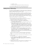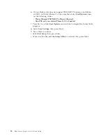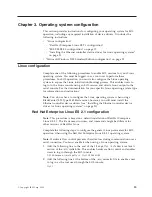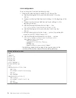
management. For a BladeCenter T unit, this enables you to have 8 simultaneous
SOL sessions active (one for each of up to 8 blade servers) with 12 additional
command-line interface sessions available for BladeCenter unit management. If
security is a concern, you can use Secure Shell (SSH) sessions, or connections made
through the serial management port that is available on the advanced management
module, to establish secure Telnet command-line interface sessions with the
BladeCenter management module before starting an SOL console redirect session
with a blade server.
The most recent versions of all BladeCenter documentation is available at
http://www.ibm.com/support/.
Hardware and firmware requirements
The BladeCenter unit must be correctly configured before you can use the
command-line interface and SOL. This section describes the hardware and software
that are required for the command-line interface and SOL.
Hardware requirements
All BladeCenter components, except for the BladeCenter HS20 Type 8678 blade
server, are SOL capable. All blade servers must be configured to enable SOL
operation. Some of the older BladeCenter components require additional
configuration to support SOL operation.
To use the SOL feature, the following hardware is required:
v
An SOL-capable blade server.
The BladeCenter HS20 Type 8678 blade server does not support SOL operation.
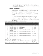
You can use the console command to control a blade server through SOL only
on blade server types that support SOL functionality that have the required
firmware levels (see Table 1 on page 3).
v
An Ethernet I/O module installed in I/O-module bay 1. For systems using
management channel auto discovery (MCAD), SOL can use I/O modules
installed in other I/O-module bays (see the
BladeCenter Advanced Management
Module User's Guide
for additional information about MCAD).
The following blade servers have specific requirements for SOL operation:
v
For the BladeCenter HS20 Type 8832 and Type 8843 blade servers, and LS20
Type 8850 blade server:
– SOL uses the first network interface, Ethernet 1 (eth1 or Planar Ethernet 1), of
the blade server to communicate. When this network interface attempts to
boot through PXE or DHCP, the network interface is reset, causing the current
SOL session to be dropped and have a new status of Not Ready. If you
require booting through PXE or DHCP, use the second network interface,
Ethernet 2 (eth2 or Planar Ethernet 2), of the blade server and install an
Ethernet I/O module in I/O-module bay 1.
– For the BladeCenter HS20 Type 8832 blade server, jumper J28 must be
installed in the correct position. See “HS20 Type 8832 SOL jumper placement”
on page 28 for information.
v
For the BladeCenter JS20 Type 8842 blade server, SOL uses the first network
interface, Ethernet 1 (eth1 or Planar Ethernet 1), of the blade server to
communicate. When this network interface attempts to use BOOTP, the network
interface is reset, causing the current SOL session to be dropped and have a new
2
BladeCenter: Serial over LAN Setup Guide
Summary of Contents for HS40 - BladeCenter - 8839
Page 1: ...BladeCenter Serial over LAN Setup Guide...
Page 2: ......
Page 3: ...BladeCenter Serial over LAN Setup Guide...
Page 6: ...iv BladeCenter Serial over LAN Setup Guide...
Page 12: ...6 BladeCenter Serial over LAN Setup Guide...
Page 30: ...24 BladeCenter Serial over LAN Setup Guide...
Page 42: ...36 BladeCenter Serial over LAN Setup Guide...
Page 56: ...50 BladeCenter Serial over LAN Setup Guide...
Page 63: ......
Page 64: ...Part Number 44R5390 Printed in USA 1P P N 44R5390...

