CAUTION
The drive train can be damaged if the lift truck is travel-
ing too fast when the controls are changed to the
opposite direction of travel.
The operator can change the direction of travel at slow
travel speeds (less than a walking speed), but the mast
must not be in a raised position. If the lift truck is moving
rapidly, slow to a walking speed before changing the direc-
tion of travel.
Inching Control
WARNING
Inching requires coordinated movement of the inching/
brake pedal and the accelerator pedal. New operators
must practice this procedure before attempting to han-
dle loads.
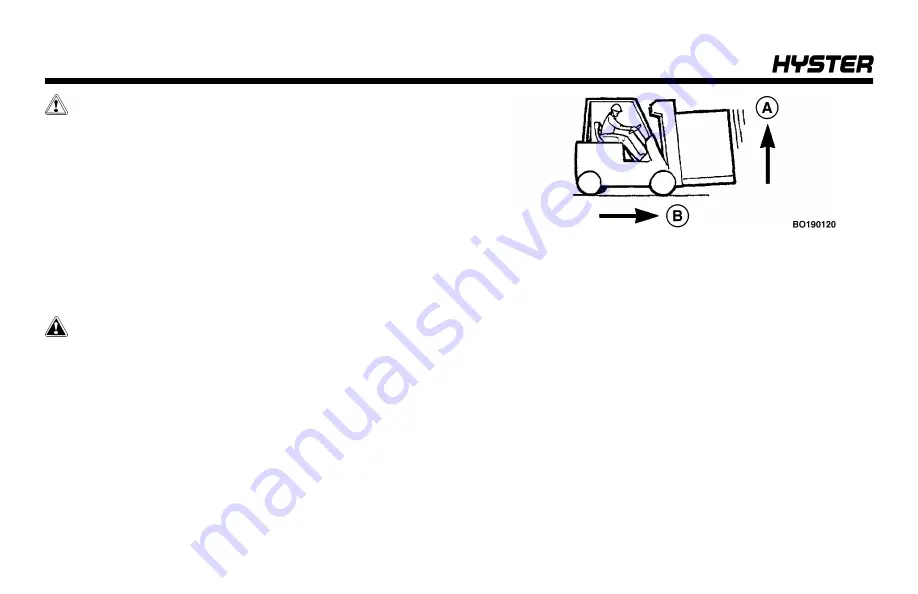
Inching is the movement of a lift truck that allows a slow
travel speed while keeping the engine speed high for fast
operation of the lift mechanism or prevents rollback on an
incline.
A.
FAST
B.
SLOW
The inching/brake pedal is used to control the inching oper-
ation. During operation as the inching/brake pedal is
applied, the clutch in the transmission gradually disen-
gages while the brakes engage.
Operating Procedures
64
Summary of Contents for H40-60XT
Page 1: ...OPERATING MANUAL H40 60XT A380 DO NOT REMOVE THIS MANUAL FROM THIS UNIT PART NO 4150900 3 19...
Page 11: ...Model Description Figure 1 Model View Showing Major Components of H40 60XT Model Description 9...
Page 16: ...Figure 3 Warning and Safety Labels Sheet 1 of 3 Model Description 14...
Page 17: ...Figure 3 Warning and Safety Labels Sheet 2 of 3 Model Description 15...
Page 18: ...Figure 3 Warning and Safety Labels Sheet 3 of 3 Model Description 16...
Page 20: ...Figure 4 Controls Model Description 18...
Page 42: ...Figure 5 Dash Display Warning and Indicator Lights Model Description 40...
Page 62: ...Figure 6 Seat Adjustment Operating Procedures 60...
Page 90: ...1 DRIVE TIRES 2 STEERING TIRES Figure 10 Put a Lift Truck on Blocks Maintenance 88...
Page 92: ...Figure 11 Maintenance and Lubrication Points PSI 2 4L LPG Trucks Maintenance Schedule 90...
Page 94: ...Figure 13 Maintenance and Lubrication Points PSI 2 4L Bi Fuel Trucks Maintenance Schedule 92...
Page 115: ...Figure 16 Seat Check Maintenance 113...
Page 120: ...1 FRAME 2 PDM 3 GROUND STATIC STRAP 4 BATTERY Figure 18 Ground Static Strap Maintenance 118...
Page 137: ...Figure 30 Brake Fluid Reservoir Cover Maintenance 135...
Page 139: ...Figure 31 PDM Showing Fuses and Relays Maintenance 137...
Page 178: ...NOTES 176...
Page 179: ...Spacer 3 19 12 18 7 18 12 17 10 17 5 17 3 17 1 17 11 16 10 16 7 16 5 16 4 16 3 16...
Page 180: ...OPERATING MANUAL H40 60XT A380 DO NOT REMOVE THIS MANUAL FROM THIS UNIT PART NO 4150900 3 19...


