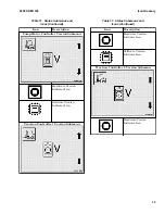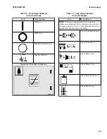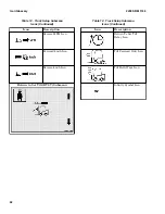
Table 12. Truck Setup Submenu
Icons (Continued)
Icon
Description
Operating Voltage Icon
Battery Capacity Icon
Full Cell Voltage Icon
Empty Cell Voltage Icon
BDI Adjustment Submenu
Parasitic Current Icon
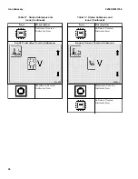
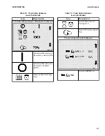
Table 12. Truck Setup Submenu
Icons (Continued)
Icon
Description
Acceleration Rates Submenu Visible to Service
Technicians only.
Low Speed Acceleration
Rate Setting Icon
High Speed Acceleration
Rate Setting Icon
Performance Type
Indicator Icon
Standard Performance
Rate Icon
Extended Shift
Performance Rate Icon
2200 SRM 1336
Icon Glossary
37
Summary of Contents for A1.3-1.5XNT
Page 6: ... THE QUALITY KEEPERS HYSTER APPROVED PARTS ...
Page 9: ...Figure 3 Technician Flowchart Sheet 1 of 4 2200 SRM 1336 Menu Flowchart 3 ...
Page 10: ...Figure 3 Technician Flowchart Sheet 2 of 4 Menu Flowchart 2200 SRM 1336 4 ...
Page 11: ...Figure 3 Technician Flowchart Sheet 3 of 4 2200 SRM 1336 Menu Flowchart 5 ...
Page 12: ...Figure 3 Technician Flowchart Sheet 4 of 4 Menu Flowchart 2200 SRM 1336 6 ...
Page 123: ......
Page 124: ...TECHNICAL PUBLICATIONS 2200 SRM 1336 2 14 8 13 4 13 12 12 3 12 12 11 ...

