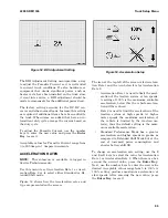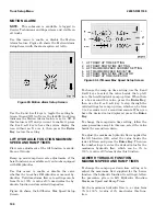
The fifth value down is the RMS (Root Mean
Squared) AC current from the motor to the control-
ler in Amperes.
When there is a Null Icon over the Forklift Truck
Icon in the top right corner of the screen, it indi-
cates traction and hydraulics are deactivated.
TRACTION MOTOR 2 STATUS
This screen is the identical to the Traction Motor 1
Status screen. It is displayed only if the truck has
dual traction motors.
OCCUPANCY SENSOR
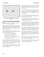
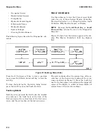
Figure 76 shows the Occupancy Sensor screen.
Figure 76. Occupancy Sensor Screen
The value to the right of the Seat Indicator Icon is
the current voltage of the occupancy sensor.
If seat belt monitoring is engaged, the seat belt sta-
tus is also shown by the icon in the lower right cor-
ner of the screen. If the occupancy sensor detects
the presence of an operator, the Seat Belt Icon is
shown; if the seat is not occupied, an X is displayed
over the Seat Belt Icon.
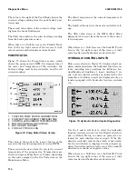
When there is a Null Icon over the Forklift Truck
Icon in the top right corner of the screen, it indi-
cates traction and hydraulics are deactivated.
BRAKE SYSTEM SENSORS
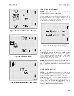
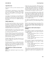
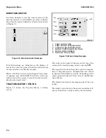
Figure 77 illustrates the Brake System Sensors
screen, which presents the current voltages of the
park brake, the brake fluid sensor, and the brake
pressure system.
Figure 77. Brake Diagnostics Screen
2200 SRM 1336
Diagnostics Menu
113
Summary of Contents for A1.3-1.5XNT
Page 6: ... THE QUALITY KEEPERS HYSTER APPROVED PARTS ...
Page 9: ...Figure 3 Technician Flowchart Sheet 1 of 4 2200 SRM 1336 Menu Flowchart 3 ...
Page 10: ...Figure 3 Technician Flowchart Sheet 2 of 4 Menu Flowchart 2200 SRM 1336 4 ...
Page 11: ...Figure 3 Technician Flowchart Sheet 3 of 4 2200 SRM 1336 Menu Flowchart 5 ...
Page 12: ...Figure 3 Technician Flowchart Sheet 4 of 4 Menu Flowchart 2200 SRM 1336 6 ...
Page 123: ......
Page 124: ...TECHNICAL PUBLICATIONS 2200 SRM 1336 2 14 8 13 4 13 12 12 3 12 12 11 ...

