AUXILIARY 2B HYDRAULIC FUNCTION
MAXIMUM SPEED AND RAMP TIMES
To change the ramp up or down time setting or to
adjust the maximum flow supplied for hydraulic
function 4B, follow the procedure given in Lift Hy-
draulic Function Maximum Speed and Ramp
Times.
Set the maximum hydraulic lift to a value from 0%
to 100%. A value of 0% deactivates this function.
Set the ramp time settings for the hoist to a value
of 0 to 2 seconds.
The setup screen for this submenu is similar to Fig-
ure 66.
OPTIONAL HYDRAULIC FUNCTIONS
NOTE:
This submenu is displayed only to logged in
Service Technicians or Supervisors.
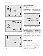
This menu allows a Service Technician or Supervi-
sor to enable or disable dual hydraulic function con-
trol. This feature allows control of two hydraulic
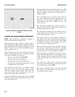
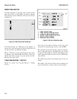
functions from a single valve. Figure 67 shows the
Hydraulic Accessories Setup Screen.
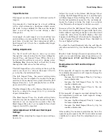
Slip Sheet: When the optional slip sheet function is
enabled the truck will enter a freewheeling state
when the truck is below a set travel speed, the ped-
als are released, and the associated hydraulic func-
tion is engaged (standard interlocks still apply). If
equipped with an automatic park brake the brake
shall be released.
Auxiliary Hydraulics: This feature enables/disables
control of a diverter solenoid allowing control of 2
hydraulic functions from a single valve. In some ap-
plications, customers may wish to add an addi-
tional function to the hydraulic system without
changing the valve assembly. In such a case, it is
desirable to redirect flow from the Aux 1, Aux 2 or
Aux 3 valves to a different function using an exter-
nal direction select valve. This solenoid valve di-
verts the A and B flow to a different function while
the main valve controls flow and direction.
Press the 2 or 3 soft key to set control of this func-
tion to Enabled or Disabled.
Figure 67. Hydraulic Accessories Setup Screen
REAR LIGHTS CONTROL
NOTE:
This submenu is available to logged in
Service Technicians only.
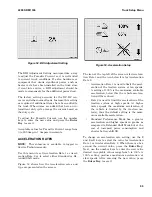
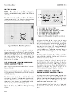
This menu permits a Service Technician to enable
or disable the outputs that control brake, tail, and
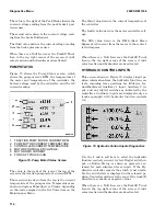
backup lamps. Figure 68 shows the Rear Lights
Control Setup Screen.
Figure 68. Rear Lights Control Setup Screen
Truck Setup Menu
2200 SRM 1336
108
Summary of Contents for A1.3-1.5XNT
Page 6: ... THE QUALITY KEEPERS HYSTER APPROVED PARTS ...
Page 9: ...Figure 3 Technician Flowchart Sheet 1 of 4 2200 SRM 1336 Menu Flowchart 3 ...
Page 10: ...Figure 3 Technician Flowchart Sheet 2 of 4 Menu Flowchart 2200 SRM 1336 4 ...
Page 11: ...Figure 3 Technician Flowchart Sheet 3 of 4 2200 SRM 1336 Menu Flowchart 5 ...
Page 12: ...Figure 3 Technician Flowchart Sheet 4 of 4 Menu Flowchart 2200 SRM 1336 6 ...
Page 123: ......
Page 124: ...TECHNICAL PUBLICATIONS 2200 SRM 1336 2 14 8 13 4 13 12 12 3 12 12 11 ...


