


Preventive maintenance
Preventive main
tenance
94
EcoSift
Operator Manual
809500
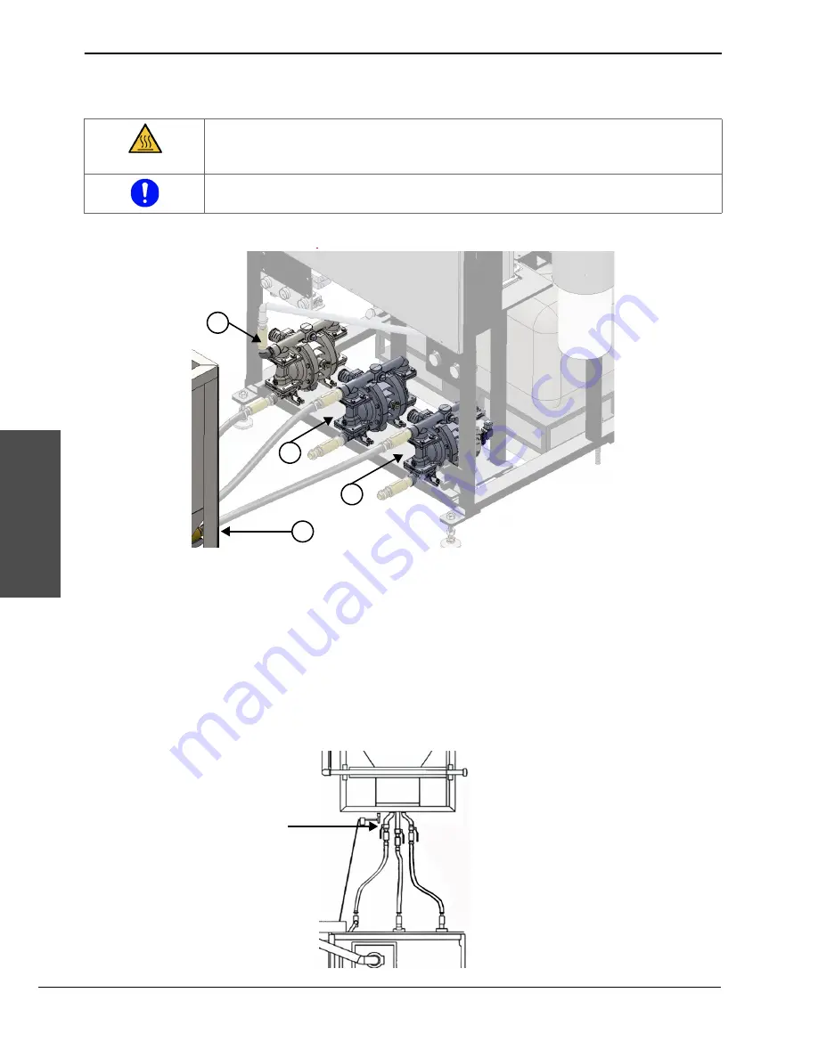
Examine the diaphragm pumps
Examine the pumps regularly to find and correct problems early.
Do this task when the EcoSift is operating.
1.
Examine the pumps for leaks, deterioration, or damage. Examine the pipes, the hoses, the fittings, and the
connections for leaks, deterioration, or damage.
Identify the source of a leak and correct the problem.
2.
Close the agitation valve on the EcoSift hopper.
CAUTION
Do not touch hot surfaces.
Repair or replace parts identified in the preventive maintenance schedule or if the parts are
defective, deteriorated, corroded, or damaged.
3
1
2
4
1
Abrasive pump
2
Feed pump
3
Agitation pump
4
EcoSift hopper
Summary of Contents for EcoSift
Page 1: ...EcoSift Waterjet abrasive recycling system Operator Manual 809500 Revision 0 English ...
Page 12: ...SC 12 Safety and compliance Product stewardship Product stewardship Declaration of conformity ...
Page 14: ...SC 14 Safety and compliance Product stewardship Product stewardship ...
Page 16: ...SC 16 Safety and compliance Environmental stewardship Environmental stewardship ...
Page 32: ...Terminology Terminology 32 EcoSift Operator Manual 809500 ...
Page 40: ...Product description Product description 40 EcoSift Operator Manual 809500 ...
Page 42: ...Options Options 42 EcoSift Operator Manual 809500 ...
Page 132: ...Troubleshooting Troubleshooting 132 EcoSift Operator Manual 809500 ...
Page 136: ...Specifications Specifications 136 EcoSift Operator Manual 809500 ...
Page 172: ...Installation Installation 172 EcoSift Operator Manual 809500 ...
Page 174: ...Technical drawings Technical drawings 174 EcoSift Operator Manual 809500 ...


