62 Non-Contact Tonometer HNT-1/1P ------------------------------------------------------------------------------------------------
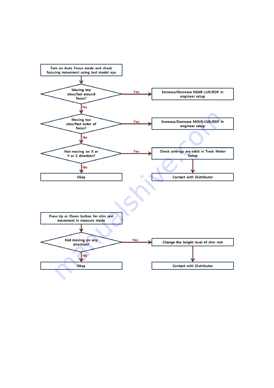
Phenomenon 7 : Auto Focus movement is unstable or not working
Phenomenon 8 : Chin rest movement is not working
Page 1: ...Service Manual Non Contact Tonometer HNT 1 1P...
Page 2: ...1 2016 2017 Huvitz Co Ltd 38 Burim ro 170beon gil Dongan gu Anyang si Gyeonggi do 14055 Republic of Korea Huvitz has the copyright to this document Parts or all of this user manual cannot be duplicate...
Page 3: ...Notice 3 2 Safety Information 4 3 Product Outline 15 3 1 Main Parts 15 3 2 Optical System 18 3 3 Electrical System 21 3 4 Measurement Flow 26 4 Repair Standard 29 4 1 Checking and Control 29 4 2 Disas...
Page 4: ...The information in this publication has been carefully checked and is believed to be entirely accurate at the time of publication Huvitz assumes no responsibility however for possible errors or omissi...
Page 5: ...operator It is for this reason that the following safety notices have been placed appropriately within the text of this manual to highlight safety related information or information requiring special...
Page 6: ...l Ce symbole identifie une note de s curit Assurez vous de comprendre la fonction de ce contr le avant de l utiliser La fonction de contr le est d crite dans le manuel d utilisation ou d entretien app...
Page 7: ...duct Symbole WEEE EU seulement Mise au rebut de votre ancien appareil Lorsque ce symbole de poubelle barr e est joint un produit cela signifie que le produit est couvert par la directive europ enne 20...
Page 8: ...dice FUSE Consult instructions for use Consulter les instructions d utilisation Type B Isolated patient connection Type B Connexion patient isol e Warning Crushing or insert of hand Attention crasemen...
Page 9: ...8 Non Contact Tonometer HNT 1 1P 2 2 2 Safety Symbol location Front View of HNT 1 P Bottom side of HNT 1 P Package Box...
Page 10: ...frequently Normal temperature for operation of the machine is at the range of 10 C 35 C and the humidity is at the range of 30 90 A place nearby a heating apparatus A place where the equipment can be...
Page 11: ...machine please keep the ambient temperature is 10 35 humidity is 30 90 and atmospheric pressure is 800 1060hpa For the Transportation of the machine please keep the ambient temperature is 40 70 humidi...
Page 12: ...Department or one of our authorized representatives 1 Light Hazard Group I according to the ISO15004 2 This device is classified as a Group I The LED used for the device is safe under expected use Ho...
Page 13: ...ophthalmologist 12 Modifications of this equipment may only be carried out by Huvitz s service technicians or other authorized persons 13 Be sure to check the safety distance before measurement If th...
Page 14: ...smoke spark or abnormal noise smell from the machine please power off immediately and pull out the plug 26 IEC standard needs to be satisfied with in order to connect an outside device with input out...
Page 15: ...r adjust this equipment and any associated accessories It is paramount that the instructions contained in this manual are fully understood and followed to enhance safety to the patient and the user op...
Page 16: ...her or not the electric power is on 3 Printer Printing the measured results 4 Measurement Button A button pressed on to measure 5 Joystick Lever Operation Lever A lever for moving object to the front...
Page 17: ...Nozzle Measuring the intraocular pressure on eyes 3 Object lens for Pachy Object lens for measuring the cornea thickness of examinees only in HNT 1P 4 Chinrest Preventing the vibration by fixing the...
Page 18: ...Non Contact Tonometer HNT 1 1P 17 1 Power Supply Socket A socket connecting to exterior power plug 2 Serial Interface Connector A terminal connecting to the exterior equipment...
Page 19: ...18 Non Contact Tonometer HNT 1 1P HNT 1 3 2 Optical System 6 e 7 8 9 10 11 12 13 14 15 16 17 18 19 19 17 20 21 22...
Page 20: ...ED to the Eye 8 Objective Lens To image the Eye to the observation camera 9 Fix Mirror To reflect the fixation LED and Pachy LED 10 Image Lens To image the Eye to the observation camera 11 Observation...
Page 21: ...y Illumination system 5 20 21 22 18 19 9 8 7 6 e G Pachy Image system e 23 24 25 19 Fix Lens To deliver the Fixation LED to the Eye 20 Pachy Ill Lens The lens for illuminate the Pachy LED to the eye 2...
Page 22: ...onometer HNT 1 1P 21 3 3 Electrical System 3 3 1 Electrical construction diagram 3 3 1 1 System functional block diagram Touch Interface SMPS IN DC12V LCD Interface Z CR X Y Motor Printer Interface Ca...
Page 23: ...22 Non Contact Tonometer HNT 1 1P 3 3 1 2 Power input electrical block diagram...
Page 24: ...ription Connector number Target connector CN2 Not used Not connect CN4 HARNESS M2_OBS CMOS OBS Camera CN5 HARNESS M2_MB TO PACHY CMOS Pachy Camera CN6 HANRESS M2_SMPS TO MB SMPS CN25 CN24 CN4 CN5 CN8...
Page 25: ...HARNESS M2_CENTER_CR_PI_LINK Chin Rest PD PI Sensor CN19 HARNESS M2_PRINTER DATA 20P Thermal Printer CN20 HARNESS M2_RS232 TO BD RS232 Connector CN22 TFT LCD FFC Cable TFT LCD Touch CN23 HARNESS M2_A...
Page 26: ...ut of Main Board 3 3 3 2 Description of IC components of Main Board ID Ref No Part Name Description 1 U3 AM1808BZWT4 TI ARM MCU 2 U29 XC6SLX25 2FGG484C XILINX FPGA Logic Array 3 U4 SST39VF3201 NAND Fl...
Page 27: ...e power switch SELF TEST Trouble Displayed error message Move to center Displayed initial screen Search for position of focus Move to position of measurement Measure the IOP Displayed output of Yes No...
Page 28: ...input PRINTER USER SETUP MEASURE RESULT Print the result of measurement Change the user setup Save Exit Display the result of measurement Enable the Pachy LED Measure the Pachy Capture pachy image Ca...
Page 29: ...Contact Tonometer HNT 1 1P 3 4 3 IOP measurement Flow Control of SOLENOID Measure the IOP Detect the signal of applanation Detect the pressure of inner part Conversion of IOP Displayed output of measu...
Page 30: ...touch any item in the screen of Engineer Setup Mode Engineering setup menus are the followings 1 Dead Pixel Correction Check the dead pixel information of cameras 2 Solenoid Control Setup solenoid pu...
Page 31: ...Log Mode Log view mode for H W initial functions 13 Print Engineer Settings Print current engineer settings 14 Move to Packing Pos Move the head to the packing position 15 Save factory settings Backu...
Page 32: ...pixels of the OBS camera on the screen 4 1 3 Solenoid Control Purpose Control the gain of Internal Pressure sensor for the better measuring graph of pressure Mode 1 Text Set power and timing of solen...
Page 33: ...test i start solenoid measure start time ii pres_idx pressure index iii max val maximum pressure value iv appl_idx1 1st peak place of graph v val 1st peak value of graph vi pres1 pressure value on 1s...
Page 34: ...chymetry LED duty B Fixation LED Fixation LED duty C External LED R Right External LED duty D External LED L Left External LED duty E Aiming LED Aiming LED duty F PD APPL LED PD LED duty 3 Use buttons...
Page 35: ...There are 4 modes SPC30 M30 SPC60 M60 and IOP offset settings 3 Press the table space to start IOP measurement setup 4 Then set the target IOP of the current model eye Adjust target IOP with 5 Press t...
Page 36: ...raph 9 Setup all the SPC ranges with a same way 10 To restore the value of setting choose Clear on the screen 11 To save the current value of setting choose Save on the screen 12 Press the offset text...
Page 37: ...tup Mode at Engineer Mode 2 Select an PWM BASE of each direction which decides base pulse width modulation of Auto Focus motor Because this is original property of motor type it is not recommended tha...
Page 38: ...ght side on X axis C DIST CONST Y UP up side on Y axis D DIST CONST Y DN down side on Y axis E DIST CONST Z FR front side on Z axis F DIST CONST Z RR rear side on Z axis 4 Press Clear button to reset...
Page 39: ...DIST X x direction B AF TARGET DIST Y y direction C AF TARGET DIST ZF front side on z direction D AF TARGET DIST ZR rear side on z direction 5 Press Clear button to reset all changes to default setti...
Page 40: ...CT Calibration vi R Setup R Calibration 3 Press the SG INFO text to show the information of the pachy LED average gray value and size i SZ means the size of the pachy LED detected over a threshold and...
Page 41: ...alibrated CCT value is working properly 9 To calibrate the R press the table space to start R Setup You can set the target R using the buttons 10 Press the Start button to automatically measure the ta...
Page 42: ...pose The touch screen is calibrated for correct touch operation Setup Procedure 1 Enter the Touch Calibration Mode at Engineer Mode or Press joystick button when the screen shows start logo and boot m...
Page 43: ...tor setup and track dist setup Test Procedure 1 Enter the Focus Align Test at Engineer Mode 2 Press Start button on the screen to check the auto tracking focusing movement 3 Check the results measured...
Page 44: ...Value of PSD sensor Psd_Anode1 Anode1 Value of PSD sensor z ratio z axis ratio 4 Press PSD button on the screen 5 Check PSD sensor value for Z axis focus level Psd_Anode0 anode0 value of PSD sensor Ps...
Page 45: ...st area X HEAD ON OFF left right direction Head Y HEAD ON OFF up down direction Head Z HEAD ON OFF front rear direction Head C REST ON OFF chin rest up down LR Measure Start test all procedures for me...
Page 46: ...to print the test results 5 The Reset button initializes all items 4 1 13 Log Mode Purpose To check logs written Execution Only if the f ram detected in the initial sequence while booting this mode i...
Page 47: ...index ix Cycle cnt The log space is limited in the physical memory So the number of log index has a cycle of writing in that space x Func detail The internal function code name xi Res meaning OK or F...
Page 48: ...ect the Move to Packing Pos button at Engineer Mode 2 Then the head and chin rest will automatically move to the packing position 4 1 16 Save factory settings Purpose Save current values of engineer s...
Page 49: ...am set your PC s COM port number 115200 Bps 3 Connect PC to HNT 1 1P with serial cable 4 Pressing the button of joystick then turn on HNT 1 1P 5 DNW program will show the following screen 6 Select Ser...
Page 50: ...2 1 Removing Head rest A ssy 1 Remove the screws 2 and then separate Head rest A ssy 1 2 Remove the bolt caps 10 8ea remove the screws 9 8ea and then separate Side cover 5 6 3 Remove the screws rear...
Page 51: ...50 Non Contact Tonometer HNT 1 1P 4 2 2 Removing the Optical System A ssy 1 Remove the screws 2 4ea and then separate Optical System A ssy 1 3 4 5 6 7 8 9 10...
Page 52: ...Non Contact Tonometer HNT 1 1P 51 4 2 2 1 Removing the Pachy Camera A ssy 1 Remove the screws pin 2 3 and then separate Pachy Camera A ssy 1 1 2...
Page 53: ...52 Non Contact Tonometer HNT 1 1P 4 2 2 2 Removing the Solenoid A ssy 1 Remove the screws 6 7 and then separate Piston Rubber 3 2 Remove the screws washer damper 2 4 5 and then separate Solenoid 1...
Page 54: ...act Tonometer HNT 1 1P 53 4 2 3 Removing the XYZ and Moving base A ssy 1 Remove the screws 4 4ea and then separate Moving base frame 2 2 Remove the screws spring washer nut 5 6 7 and then separate XYZ...
Page 55: ...54 Non Contact Tonometer HNT 1 1P 4 2 4 Removing the XZ M A ssy 1 Remove the screws 3 and then separate XZ M A ssy 2...
Page 56: ...ontact Tonometer HNT 1 1P 55 4 2 5 Removing the Locking Module A ssy 1 Remove the screws 3 and then separate Locking Stopper A ssy 1 2 Remove the screws 8 4ea and then separate Locking Module A ssy 6...
Page 57: ...56 Non Contact Tonometer HNT 1 1P 4 2 6 Removing the XZ RAIL A ssy 1 Remove the screws 2 and then separate XZ RAIL A ssy 1...
Page 58: ...NT 1 1P 57 4 2 7 Removing the Connector Main Brkt A ssy 1 Remove the screws 7 and then separate Connector Main Brkt 1 2 Remove the screws 5 and then separate INLET 4 3 Remove the pcb support nut 8 9 a...
Page 59: ...g is displayed The screen is moving The aiming spot is not displayed The anterior part of eye is not displayed 3 Troubles related with measurement NO TARGET is displayed ERROR is displayed IOP measure...
Page 60: ...Non Contact Tonometer HNT 1 1P 59 Phenomenon 1 When Power is On there is no action Phenomenon 2 LCD monitor display nothing But other functions works...
Page 61: ...60 Non Contact Tonometer HNT 1 1P Phenomenon 3 Key does not work...
Page 62: ...act Tonometer HNT 1 1P 61 Phenomenon 4 When printing out there is some unclean side especially end of paper Phenomenon 5 When printing paper is not fed correctly Phenomenon 6 Cannot see the eye fixati...
Page 63: ...62 Non Contact Tonometer HNT 1 1P Phenomenon 7 Auto Focus movement is unstable or not working Phenomenon 8 Chin rest movement is not working...